|
Untitled Page
ARCHIVED FORUM -- April 2007 to March 2012
READ ONLY FORUM
This is the first Archived Forum which was active between 17th April 2007 and
1st March February 2012
Latest post 02-20-2012 4:42 PM by sonavor. 215 replies.
-
-
 Søren Mexico
 
 - Joined on 09-13-2007
- Mexico city
- Posts 1,621

|
Re: Beomaster 6000 Refurbish
Monday, was working hard for 10 hours, but I have to see what happens here, its getting near to conclution and I I'm so impressed.
Beosound 3000, BL 4000, BL 8000, BG 2404,BG 5000, BG CD50, Beocord 5000, BM 901, BM 2400, BM 4000, BV S45, BV 3702. There is nothing we cannot do, but a lot of things we don't want to do!!
|
|
-
-
sonavor
  - Joined on 02-13-2011
- Texas
- Posts 193

|
Re: Beomaster 6000 Refurbish
Here is what happened today - A step or two backwards.
At the start of the day the Beomaster was operational except for the FM tuner display and the volume level lamps not being bright enough. At the end of the day the FM tuner is out of alignment.
To take care of the lamps I ordered replacements from Dillen. I also ordered some other LEDs to try out.
For the tuner frequency display I had decided that there was some problem with the signal coming from the tuner board because I wasn't seeing anything across IC8 pins 2 and 3 (the prescaler inputs hi and lo respectively). I removed the metal shield box over the 08 module circuit that feeds the signal to the prescaler and checked the 8D1 diode pair and the 8TR2 transistor. The tested good. With the cover off that circuit I tried to take some signal measurements. I couldn't get any.
>>> I made a mistake at this point by not double checking that the tuner was still tuning in stations. <<<
I put the tuner board circuit back together and decided to run some tests again of the circuit on the 02 module that delivers the signal to the prescaler. This is when I noticed that the tuner wasn't tuning in the stations properly. During my testing somewhere I knocked the tuner out of alignment. So a new task.
Instead of two remaining problems I now have three. I could still say two I guess since the lamps for the volume control are on their way -
1. Perform the service manual tuner adjustment procedures. The problem here is there are some steps in the procedures that say to tune the Beomaster to a certain frequency. Since I have no frequency read out I'll have to find some work around.
2. Determine if the new prescaler works or not. I did try using a signal generator to send a low voltage : around 0.4V p-p at 1MHz across IC8 pins 2 and 3. I measured the output - pin 7 and did see a waveform. It didn't look like a nice square wave like I thought it should and the frequency isn't 1/64 of the input frequency. I attached a picture of the oscilloscope measuring the IC8-2/3 input and the IC8-7/gnd output.
I suspect the IC8 prescaler - U264B is not good now. I tried the original U264B in this test and it has no output at all. However, the output I see on the new one looks pretty low to me. I expected a nice clock signal like I saw on the output of the timebase counter. So I will have to about purchasing another one. But I don't want to risk another one until I know the signal from the tuner board is good. 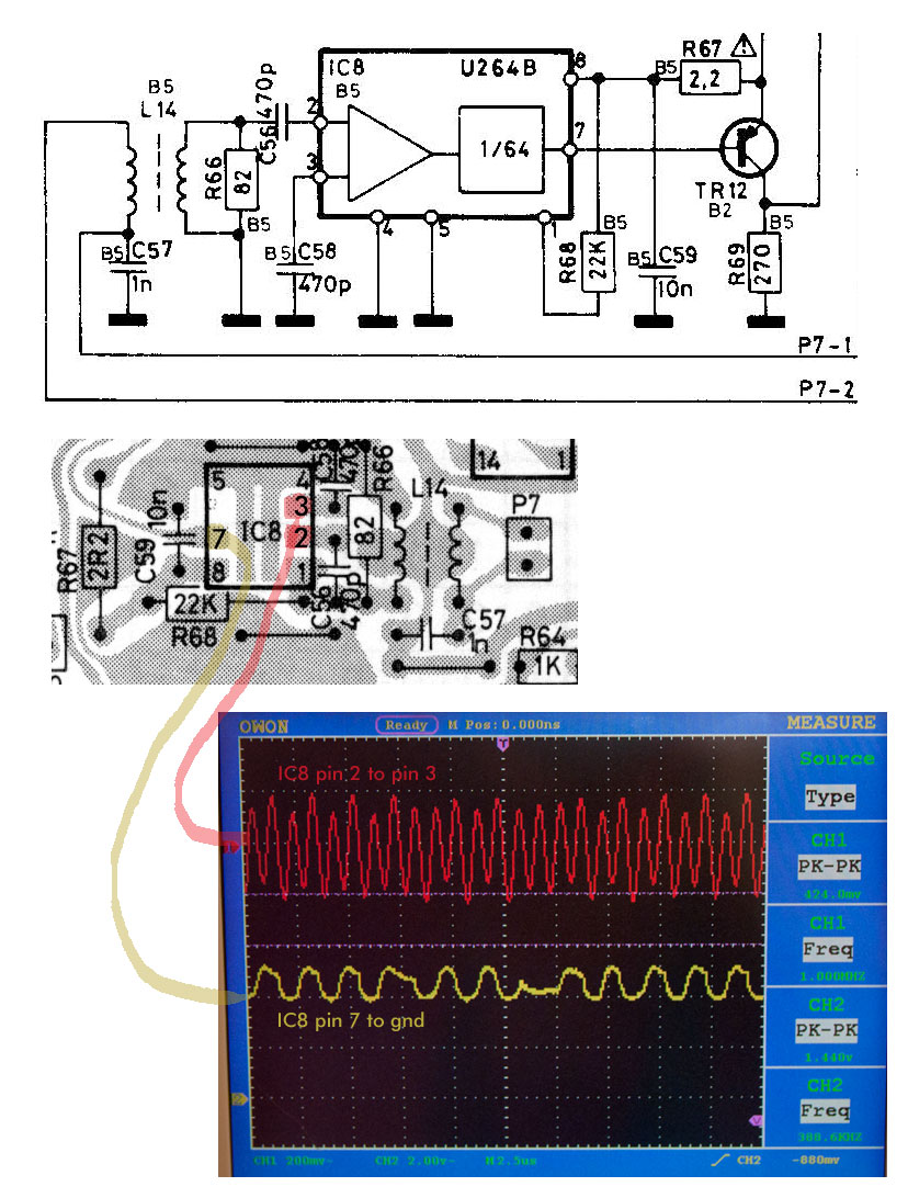
|
|
-
-
tournedos
  - Joined on 12-08-2007
- Finland
- Posts 5,808
|
Re: Beomaster 6000 Refurbish
Sorry if I'm late to say this, but FM frontends (and IF alignment) should be left well alone unless you know there's something wrong in there 
Concentrate on the simple things. Have you checked that the U264B has a good, stable power supply?
Also, don't inject the test signal directly on pins 2&3. Unless your signal generator has a balanced floating output, it's not going to work. Inject the signal the same way it would come from the tuner, i.e across R66.
Unfortunately I couldn't find the U264B datasheet anywhere (short of registering on a Polish forum I don't care enough to do), but it's possible it won't work with signals as low as 1 MHz. It's specified to go up to 1 GHz and the local oscillator signal from the tuner would be around 90 MHz.
|
|
-
-
sonavor
- Joined on 02-13-2011
- Texas
- Posts 193
|
Re: Beomaster 6000 Refurbish
I should have shown the signal generator lines in my picture. They were applied across P7 pins 1 and 2 going 2L14 to simulate a signal coming in from the tuner board.
I am brain dead though...The reason I am never reading a signal from the tuner board is because I only have a 25MHz oscilloscope. I put that out of mind thinking that I wasn't going to be looking at any FM frequencies directly (which I wasn't initially). Then when I switched over to start looking at the tuner I completely forgot about the limitation of the scope. I cranked the frequency generator up to 90MHz and sure enough, my scope shows nothing. In addition, the prescaler is designed for FM frequencies of course.
So now, with 90MHz applied directly on the 02 board J7 connector pins 1 & 2, I can monitor the signal coming out of the prescaler (2IC8 pin 7) and see that it is 1/64th of 90MHz so in scope range. I can also see that 2IC4 (processor) pin 38 has a square wave going into the frequency counter that is 1/8 of the output of prescaler (also in scope range). With that condition though, the frequency display on the Beomaster is still showing 74.8. I was expecting it to show 90MHz.
All of this still leaves questions - Why am I not seeing any prescaler activity when the tuner board is supposed to be supplying the signal to the prescaler? Is the frequency display problem still something with the prescaler? 
|
|
-
-
sonavor
- Joined on 02-13-2011
- Texas
- Posts 193
|
Re: Beomaster 6000 Refurbish
I am wondering about the clock signal into the processor frequency counter input (2IC4 pin 38). In that last picture of the scope measurement the 2IC4 pin 38 signal looks like it has the correct frequency for the 90MHz signal being generated (to simulate the tuner). The voltage level looks like it could be a problem though. The IC that sends that signal to the processor is the mod chip B&O added. It is a 74LS74AN and the datasheet says the its output high voltage level is typically 3.4v witha minumum of 2.7v. What I am seeing is 1.28v. If that isn't sufficient for the processor to read then it could explain why the display stays at the default 74.8 instead of the actual frequency.
|
|
-
-
sonavor
- Joined on 02-13-2011
- Texas
- Posts 193
|
Re: Beomaster 6000 Refurbish
Did a quick test and got an answer.
After removing the 74LS74AN chip (B&O mod IC) from the socket, I injected a 3.5v square wave in the socket - pin 9 (output to the IC4 pin 38 frequency counter input). That gets the display working again! I can vary the frequency on the generator and monitor it on the Beomaster display. Whew!
So here is where I think I am on this -
1. I believe the new 2IC8 prescaler is still fine.
2. The 2IC4 processor is good.
3. The mod IC 74LS74AN is not supplying a high enough clock signal for the processor to count. The frequency is correct but the voltage level isn't. So I need to investigate this. Might just need a new 74LS74AN (I have a couple of spares) or there is a problem with the +5 supply (kind of unlikely since the other ICs are working).
4. Once I can get the frequency display working I will need to use it to do the tuner adjustments. Boy I wish I hadn't messed that up. On the positive side though, it will be a good thing to learn. 
|
|
-
-
tournedos
- Joined on 12-08-2007
- Finland
- Posts 5,808
|
Re: Beomaster 6000 Refurbish
 sonavor: sonavor:It is a 74LS74AN and the datasheet says the its
output high voltage level is typically 3.4v witha minumum of 2.7v.
What I am seeing is 1.28v. If that isn't sufficient for the processor to
read then it could explain why the display stays at the default 74.8
instead of the actual frequency.
Yes, if nothing is
overloading the output and the chip is getting a correct supply voltage,
that is definitely too low to count as a digital high for the processor
(it wouldn't be enough even for TTL inputs, and I believe the processor
is a MOS chip, which would rather see > Vcc/2).
Check the
supply, double check the connections (as you had the mod board
completely out?) and if everything seems otherwise OK, replace the chip.
Don't worry too much about the tuner alignment yet; if you
haven't turned any coil cores or something, it should still be
reasonably easy to get it right.
EDIT: you might want to check what pin 8 of that LS74, now unconnected, looks like; it is a logical complement of the pin 9 signal that goes to the processor.
|
|
-
-
-
sonavor
- Joined on 02-13-2011
- Texas
- Posts 193
|
Re: Beomaster 6000 Refurbish
Good idea mika. For this test I used the FM signal generator again to supply a 90MHz signal to the J7-2,1 connector on the 02 module. I also put the original 74LS74AN IC back in and verified that it too had too low a Vout on pin 9. It did. The complement Vout, Pin 8, is a nice 4v p-p square wave though. So I removed the wire from pin 9 to the processor (IC4) pin 38 so there would be no load and now pin 9 is a 4V p-p square wave. The 5v supply to the L4LS74AN chip is a hair over 5vdc. The connection from the 74LS74AN IC to IC4 pin 38 is a direct connection. There aren't any other components - no pull-ups or anything so I guess it is the processor loading down the output.
|
|
-
-
sonavor
- Joined on 02-13-2011
- Texas
- Posts 193
|
Re: Beomaster 6000 Refurbish
No real breakthroughs tonight but I did get some additional information.
As Mika suggested I rechecked the wiring on the 8002562 mod board. I didn't find anything wrong but with a lack of solid leads I decided to rewire it (carefully and with anti-static protection). When I was done my first attempt was to pull the P26 connector at the 08 tuner board and inject a 100MHz signal with my FM signal generator. I put a replacement 74LS74AN IC in the mod board. When I powered up the Beomaster and selected the tuner "P" I could see information on the tuner display other than the 74.8. I measured pin 9 of the 74LS74AN chip and it was a 4v square wave as it should be. Quickly after that the display started to jump around to different values like it was unstable. I measured pin 9 again and the peak-to-peak voltags was dropping. It was in the 2.4v range now. Eventually it got down under 2v and the display stopped moving. It was showing something like 40.2 but that was just random. When I powered the Beomaster off and on again the display was back to 74.8.
I stopped for a while to think what to try next. I decided to take out the 14 pin IC socket and return to the original 74LS74AN IC...just to cover that case. I ran the same test as before and got pretty much the same result. The Beomaster had been sitting a while and on power up it had 4v p-p square wave on the ICmod pin 9. Then it started losing strength down to where the display became unstable, then frozen. I guess that tells me the problem occurs due to something warming up or charging up.
The +5v power for the mod chip also looked good. I measured it from its Vcc pin to its ground and it was always at +5v. I even tested pulling the chips power and ground and running it directly to my DC power supply. The result was the same. Pin 9 gets loaded down. One thing about the signal on Pin 8 and 9 - both have a +3.5vdc offset. I don't know if that is normal or not but I just measured it tonight.
One other test I tried was to use the 08 tuner board's signal for the FM frequency detection instead of my generator. I didn't get anything on the 74LS74AN pin 8 or 9. I was getting music from the tuner through my headphones though so the tuner was tuned to something. The tuning is still off though but I can bring in a couple of stations.
|
|
-
-
tournedos
- Joined on 12-08-2007
- Finland
- Posts 5,808
|
Re: Beomaster 6000 Refurbish
That's odd - would be nice to know what the actual impedance of the
processor input is. If I remember right, you've never seen a proper
tuner freq display so far? This problem might have been there all along
then, even before you started the work.
The LS74 datasheet says that a H level output should be able to supply 0.4 mA
while keeping the voltage at the specified level, 2.7V minimum (3.4V
typical). Seems like the processor is sucking up more than that. I have
no idea what may have caused that, but as you already tried to supply
the processor pin with a direct test signal and it worked, it should be
safe to help the LS74 a bit... try adding a 10k or so pull-up from pin 9
to +5V. It's just half a milliamp more and might be enough to satisfy the processor input. The LS74 will have no trouble pulling it down for L level.
EDIT: what do you mean with "+3.5V offset"? In reference to what? Do you possibly have the ground missing from one of the boards now that you have everything open...?
|
|
-
-
Step1
 
- Joined on 07-06-2008
- Manchester
- Posts 961
|
Re: Beomaster 6000 Refurbish
either that or the ls74 piggy board ground is connected in the wrong place!
tournedos:
That's odd - would be nice to know what the actual impedance of the
processor input is. If I remember right, you've never seen a proper
tuner freq display so far? This problem might have been there all along
then, even before you started the work.
The LS74 datasheet says that a H level output should be able to supply 0.4 mA
while keeping the voltage at the specified level, 2.7V minimum (3.4V
typical). Seems like the processor is sucking up more than that. I have
no idea what may have caused that, but as you already tried to supply
the processor pin with a direct test signal and it worked, it should be
safe to help the LS74 a bit... try adding a 10k or so pull-up from pin 9
to +5V. It's just half a milliamp more and might be enough to satisfy the processor input. The LS74 will have no trouble pulling it down for L level.
EDIT: what do you mean with "+3.5V offset"? In reference to what? Do you possibly have the ground missing from one of the boards now that you have everything open...?
|
|
-
-
sonavor
- Joined on 02-13-2011
- Texas
- Posts 193
|
Re: Beomaster 6000 Refurbish
That is correct about never seeing a real working frequency display on this unit. When I first got the 6.5v problem fixed where the Beomaster would start working (prior to the issues with the reset line), I briefly was able to tune stations and see the proper value in the display. But just like now, that only lasted a short bit before the display started jumping around to random values (now I know why).
I was wondering about the ground too but it measures solid and too make sure it wasn't the ground (or Vcc) I used my external DC power supply to provide 5v power to the chip across Vcc and Gnd.
The pull up option sounds like a good thing to try. Thanks.
Edit: Forgot to add - I have all of the boards in the Beomaster for these tests and all of the ground wires are secure on their attach points. The offset is just what I measure on the oscilloscope when I switch the scope probe to DC coupling. I made the measurements of the digital signals with the probe ground connected to the ground on the 02 module board.
|
|
-
-
tournedos
- Joined on 12-08-2007
- Finland
- Posts 5,808
|
Re: Beomaster 6000 Refurbish
Still... what did you mean with "+3.5V offset"?
|
|
-
-
sonavor
- Joined on 02-13-2011
- Texas
- Posts 193
|
Re: Beomaster 6000 Refurbish
When looking at the measurement on the oscilloscope, if I set the probe input to use DC coupling then the clock signal inputs I see on pin 8 and 9 shift up about 3.5v on the display. When I set the probe to use AC coupling the DC offset is ignored and I only see the clock signals on the display. I was just wondering if that is what is expected.
|
|
-
-
tournedos
- Joined on 12-08-2007
- Finland
- Posts 5,808
|
Re: Beomaster 6000 Refurbish
AC coupling floats the displayed signal so that it is zero on average, regardless of what the lows and highs of the incoming signal are.
Look at the absolute voltage levels in DC mode; L should be very near to 0V / gnd (first adjust your scope's vertical scale to show 0 with no signal applied).
|
|
-
-
sonavor
- Joined on 02-13-2011
- Texas
- Posts 193
|
Re: Beomaster 6000 Refurbish
It will have to be tonight before I can measure it again but when I made the earlier measurements I did cycle through to the ground coupling to check where that line was. I will need to re-measure the other logic signals to know where they all are. Last night though I was just measuring the 74LS74AN chip and noticed the offset. That offset is from the ground coupling level I checked and the lo level of the signal I was measuring (with the coupling in DC mode). I was too tired to think about checking the offset level on the other signals but I will do that. As you mentioned, this problem could have been a long time problem with this particular unit. I'm going to try and contact the seller and see if he remembers anything about that. Remember, he included it with the Beogram CDX because he wanted to get rid of it and even told me it wasn't in working condition. So it was a sick Beomaster and I am hoping I can cure it.
|
|
-
-
sonavor
- Joined on 02-13-2011
- Texas
- Posts 193
|
Re: Beomaster 6000 Refurbish
Tonight was a little better.
Earlier today I found out that another option is to use a different version of the flip-flop chip...one with better drive capabilities. So I ordered a couple 74ACT74 and 74HCT74 flip-flops from Mouser (didn't have time to drive over there). They are scheduled to mail out tomorrow so, hopefully, they will arrive on Saturday.
In the meantime I went ahead and tried the pull-up to 5V. It was suggested to me to use a 1K ohm resistor so I started there. The only one I had was a 1/4W but it is tiny so fit nicely on the 8002562 mod board between Vcc and the wire taking the clock signal over to the processor.
The result of the pull-up was not successful however. In the picture of my scope measurements tonight - the top picture is of the 74LS74AN flip-flop pin 8 (complement to the output used). It isn't connected to anything so it shows a non-loaded, good clock signal. The second picture is of the flip-flop output used - Pin 9. As you can see it has an offset (which measures around 3.7V). The clock signal itself is only 1.4V peak-to-peak. That picture is the same whether my pull-up resistor is in place or not. Looking at that clock output I realized the problem wasn't that the signal could go up to 4 or 5 volts. The problem is that it can't drive the signal low.
So the third picture is with the 1K ohm resistor moved so it is now between the output clock signal (to the processor) and the 74LS74AN ground. That worked (kind of) and I got a decent clock signal for the processor to measure...it's almost 4V p-p.
The above measurements were made with a test FM signal from my signal generator (between 90MHz and 100MHz) so the next step was to try the Beomaster tuner board signal. When I tried that I got some display numbers jumping all around until they froze. I measured the flip-flop pins 8 and 9 and there was no signal. So still think I have a problem coming off that tuner board. I also don't think the pull-down is going to be a final solution. That is because when I connect the signal generator back up I am getting an output intermittently. The pin 8 complement always has a good clock signal but the pin 9 is now unstable. There is definately some problem between my 74LS74AN flip-flop and the IC4 processor pin 38 input. 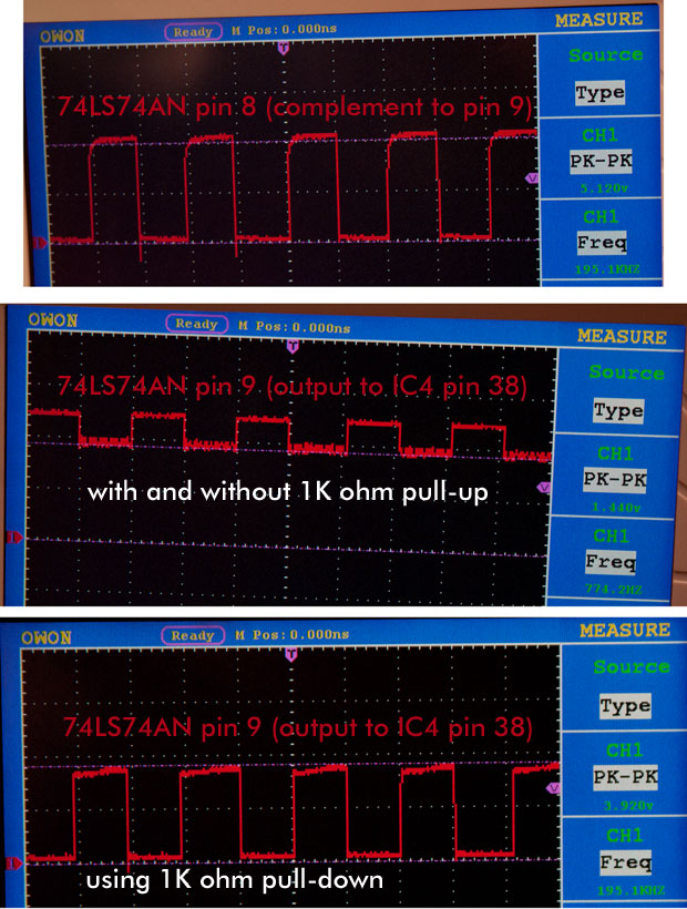
|
|
-
-
-
sonavor
- Joined on 02-13-2011
- Texas
- Posts 193
|
Re: Beomaster 6000 Refurbish
With the pull-down resistor removed and the Beomaster back to it's normal configuration (just a wire between the flip-flop mod chip pin 9 and the IC4 pin 38) - the IC4 pin 38 to ground measures 116.7K ohms. How does that compare to your BM6000? Do you have any specs on the processor IC regarding inputs, outputs and type of device?
I hear what you are saying about any modifications but with the unloaded flip-flop output having a good clock signal, then having the problems it has when only connected to the IC4 pin 38 I am not sure what else to look at. I have checked that connection several times. I have also tried a different 74LS74AN IC when I had a socked on the mod board. Right now the socket is out so I am back to the original way the flip-flop was installed.
Another clue is that after the Beomaster has been sitting for a long time, the signal into IC4 pin 38 starts out good...but only for a minute or so. The problem begins when something warms up or charges up I guess. However, on this signal there are no other components connected to the connection other than the flip-flop and the processor.
For now I am going to wait until I get the new flip-flop ICs before I try anything else. Hopefully, that will be Saturday.
|
|
-
-
sonavor
- Joined on 02-13-2011
- Texas
- Posts 193
|
Re: Beomaster 6000 Refurbish
My order of flip-flops from Mouser arrived today.
I'll get right to it - the result is mixed.
I ordered more than one brand and type of flip-flop since they were low cost and I had to pay $6 shipping regardless of how many I ordered. The first one I tried was a Fairchild MM74HCT74N IC. It worked a little better than the original 74LS74AN in that the output to the processor pin 38 was able to drive a little lower. The overall clock signal wasn't the full range like the complement side.
The next flip-flop I tried was a ON Semiconductor MC74ACT74NG (5V CMOS). It worked pretty well ...for a bit. I didn't measure the time but it was about 5 minutes I think. It stopped working completely so I think a might have died.
I tried one more - a TI CD74HCT74E. It had a good looking output signal but it wasn't quite low enough to consistently trigger the processor pin 38 for it to count it. I have a TI CD74ACT74E that I will try later since the ON Semiconductor 74ACT74 worked fairly well...but I want to check that the other one didn't fry first.
I checked the clock signal source for this signal from the 2IC9 counter and saw that it gets affected when the flip-flop gets loaded (which makes sense). So the problem seems to be centered around the flip-flop chip having trouble driving the processor pin 38. I have checked and double-checked the ground and +5V to the flip-flop (I've actually rewired it a couple of times in working on this). It has consistently measured good.
|
|
-
-
sonavor
- Joined on 02-13-2011
- Texas
- Posts 193
|
Re: Beomaster 6000 Refurbish
Does anyone know what type of device the BM6000 IC4 processor is (TTL, CMOS)?
|
|
-
-
sonavor
- Joined on 02-13-2011
- Texas
- Posts 193
|
Re: Beomaster 6000 Refurbish
I setup a breadboard test of the ON Semiconductor 74ACT74 flip-flop I thought might have died. It is still alive. I can setup similar conditions of the signals in and out of the flip-flop in the Beomaster on the breadboard and it works fine. I have no idea why none of these flip-flops can keep the IC4 processor (pin 38) happy. I am back to suspecting the processor (for the third time) as the +5 power and grounds all appear to be good.
I am probably going to rest this job for a while...at least until my volume lamps arrive from Dillen. I do have in this Beomaster 6000 a receiver that will function as an integrated amplifier right now. It drives some RL140 speakers quite well. I still hope to get the tuner section and tuner display repaired eventually but that will most likely require me finding another unit for parts. I am going to pull the hard to find IC8 prescaler out and store it somewhere safe for now though as I don't want to risk anything while it isn't being used.
In the meantime I am switching to a mechanical task and got one of my MC120.2 speakers cleaned up, ready for the new foam surround for its woofer. It was kind of nice just listening to music and doing some non-electrical work after the last several weeks (Beomaster 4000's and this 6000).
|
|
-
-
tournedos
- Joined on 12-08-2007
- Finland
- Posts 5,808
|
Re: Beomaster 6000 Refurbish
sonavor:
Does anyone know what type of device the BM6000 IC4 processor is (TTL, CMOS)?
It's a mask ROM version of Mostek MK3870, which in turn is a single chip implementation of Fairchild F8 - which was a pretty archaic architecture already in the early '80s...
The F8 was an NMOS chip - the day was too early for CMOS, and the chips too complex for TTL. One shouldn't extrapolate too far, but I suppose the electrical characteristics of the BM6000 processor would be similar to F8, and its short form datasheet is here. I had no luck searching for the Mostek data sheet.
I_il for most of the input pins is around one milliamp, and none of the logic families you've tried as the *74 should have no trouble sinking that. If there really is nothing wrong with the supply voltages (even after stuff has warmed up) I would tend to put my money on a faulty CPU. That will be hard to confirm without trying a known good extra CPU module.
Nevertheless, if the pulses stop coming from the tuner module to the U264, that isn't your only problem, and we should concentrate somewhere else. I bet we will all feel rather stupid when it turns out to be something silly & simple.
|
|
-
-
sonavor
- Joined on 02-13-2011
- Texas
- Posts 193
|
Re: Beomaster 6000 Refurbish
Thanks for the link Mika. I agree, the flip-flop ICs shouldn't have any problem driving the processor...plus that is how they came from the factory and there were no problems. In my case though, that one signal is having problems. There is a problem with the tuner but that is my own created issue. I'm going to rest the project for a while and think about it.
Today I refoamed my Beovox MC120.2 speakers. Those woofers had to be the easiest to refoam that I have encountered so far. The Beomaster 6000 drove a pair of RL140's the whole time I was working on the refoam without any problems. I was using an ipod on TP2 as the music source. After I was done the heatsinks in the back of the Beomaster were not hot like they used to get.
Here's a picture of the Beomaster 6000 connected to the RL140's and two pictures of the MC120.2 with the woofers refoamed. I still need to do a little repair on each speaker's plastic grill port (on the base of the cabinet). Medogsfat post on the MC120.2 refurbish shows all of that. There are three grill cover pins that I also need to repair. I will use the mod to Medogsfat fix for those. I have some stands for the speakers as well but I need to sand and repaint them. 
|
|
|
|
|