|
Untitled Page
ARCHIVED FORUM -- April 2007 to March 2012
READ ONLY FORUM
This is the first Archived Forum which was active between 17th April 2007 and
1st March February 2012
Latest post 02-20-2012 4:42 PM by sonavor. 215 replies.
-
-
 Step1
Step1
 
 - Joined on 07-06-2008
- Manchester
- Posts 961

|
Re: Beomaster 6000 Refurbish
What you are hearing is the relay that switches the power to the amplifier. This is switched from a transistor on the volume control board which in turn is switched from the processor standby line. If the processor is not working correctly then I would ignore this click as it is a result of the fault not the cause.
When this P is displayed check the 6.5v supply line and again when things are working normally. If the thing is going into standby this might be an amp issue again disconect to minimise other problem areas.
I would forget about teh 5v line for now this is very unlikely to be a problem as well!
|
|
-
-
sonavor
  - Joined on 02-13-2011
- Texas
- Posts 193

|
Re: Beomaster 6000 Refurbish
You are referring to the Output Amp (09 Module), right? On that board I replaced the electrolytics and the trimmers for idle and offset. I'll start looking at the voltages there next.
One of the original problems with this receiver when I got it was that it would play for a while then shutdown. The shutdown was such that it did not go into standby. It just completely powered off and would not power back on. Even disconnecting the power plug for a while and back in wouldn't revive it. When I started working on it I discovered it came back to life when I brought power up slowly with the variac. It is sounding like the problem I have now might be related. Three electrolytic caps on the 09 board had measured bad and if you look back at the pictures on page one of this thread you can see some discoloration on the board from heat.
|
|
-
-
chartz

- Joined on 07-20-2009
- Burgundy
- Posts 984
|
Re: Beomaster 6000 Refurbish
Wow. It almost looks like a miracle that mine should work at all. I'm looking at it with a worried eye...
I can't help on this one, sorry about that, but I'm looking forward to the conclusion!
PS: It seems that I haven't received any notification for some time, although subscription is 'on'.
|
|
-
-
sonavor
- Joined on 02-13-2011
- Texas
- Posts 193
|
Re: Beomaster 6000 Refurbish
I think a recap on yours would be pretty smooth. You have one that is working good already. The one I have was given to me along with a Beogram CDX for $25 ... with the understanding that the CDX had the hinge problem and that the Beomaster 6000 did not work. When I got it home and tested it on my dim bulb/variac tester the power came on and it was working. The controls were scratchy and the tuner frequency display was stuck but it drove a pair of RL 140 speakers okay. I used it like that for a while after ordering update parts from Dillen. Then one day it just shut down while playing. So I think this unit had some pre-existing problems that I am now able to get to. It definately isn't just a recap task. I'm not complaining though. The price was right and while a little frustrating at times, I kind of enjoy restoring a unit like this....providing the final result will be a receiver I can use. Except for the processor chip and displays I think replacement parts for the other components can be found. I am tempted to take a break and refoam the woofers on my MC120.2 speakers. I've never listened to them so I am getting anxious to get that task done too. But, I'll keep plugging along on the Beomaster until it's fixed or have to wait on a part.
|
|
-
-
Step1
- Joined on 07-06-2008
- Manchester
- Posts 961
|
Re: Beomaster 6000 Refurbish
Like I said Sonavor, disconnect the amp power plug for now and get the reciever running in a stable manner, then you can reconnect the amplifier and sort any further problems out that then arrise.
You are doing well. Might not harm to have a night off though!!!
|
|
-
-
sonavor
- Joined on 02-13-2011
- Texas
- Posts 193
|
Re: Beomaster 6000 Refurbish
Module 11 is the Fuse and Relay board. The relay (RL1) on that board is what I am hearing, right Olly? It is controlled by a circuit on the O6 Modlue - Motor Control board which is marked as the uC Supply (+5v to the processor). I am getting ready to monitor those components.
I did what you said and disconnected the connectors from the 09 Module (Output Amplifier). The toggling between Standby and "P" continues without the 09 board so I'm good to trouble-shoot without it connected. Before I disconnected the 09 Module though, I was curious what the idle voltage across the emitter resistors and what the offset voltage was at the speaker outputs (per the service manual). With power on and the unit out of standby I was able to make the idle and offset adjustments without any problem. The voltages were already very close.
|
|
-
-
sonavor
- Joined on 02-13-2011
- Texas
- Posts 193
|
Re: Beomaster 6000 Refurbish
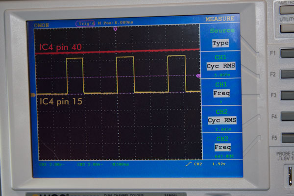
I figured out that the relay and circuit controlling the relay are just results of the problem. The relay turns the +50/-50 V supply off. So when the unit is in standby that power is not supplied...which makes sense. So as Olly was saying, the relay is controlled by the standby signal. I disconnected the relay. After adding test points to the 02 module to monitor the +5 V supply to the processor, the +V supply to the standby output circuit, the processor timbase (IC4 pin 15) and a couple of other signals I wanted to look at, I saw that all of the voltages looked good. The Beomaster was still toggling between standby and the "P" error mode (as opposed to "P" tuner mode). The relay was out of the circuit so I didn't have to listen to all of the clicking. The +5 volt lines and timebase processor clock were clean and didn't waiver. Occasionally the Beomaster would remain in standby mode for a bit so I would put it into a valid mode like PH. It would stay in PH mode for a random length of time, then it would switch back to either standby or the "P" error mode.
I feel like I am in a circle now and I am suspecting a bad IC4 processor again. Not a dead processor, but a faulty one. To eliminate other things as being faulty I have disconnected them. The 09 Module (Output Amp) is already disconnected so it had no effect. The 08 Module (FM tuner) is disconnected - no effect. I alternated disconnecting the remote control and the keypad. I also tried both the keypad and remote control disconnected - no effect. That left just the 03 Module. As the others, it didn't affect the problem.
Since the volume control works, the input select (keypad/remote control) work, the clocks look good - I am thinking that the IC4 chip must have an internal problem where it randomly jumps to a different mode. It's not a matter of the display just being wrong either. When the "P" error mode is displayed, the other buttons, like volume and mode select, don't function.
Here is a picture of the IC4 processor chip +5v power (pin 40) and the timebase (pin 14).
|
|
-
-
sonavor
- Joined on 02-13-2011
- Texas
- Posts 193
|
Re: Beomaster 6000 Refurbish
One more post tonight...
I took a short break and was thinking over what I had tried. Then I reviewed suggestions from the Beoworld forum and came across some notes from early on. Dillen had mentioned that I needed to look out for the reset line (and there is a trimmer in that circuit too). I had measured that back when it was originally stuck in the "P" error mode and wouldn't budge. At that time the reset line was in a steady state (+5v). I had tried to force it to ground to see if the processor would come alive but that was also back when I wasn't getting the timebase clock signal. I had mentally written that off as a suspect. Now that the timebase is working and I have the processor kind of working I realized I haven't even looked at the reset line. So I just took a look at it with the scope and monitored the line (IC4 pin 39). Everytime the mode switched from standby to the "P" error mode and back there was a pulse on the reset line. That line also appears to be noisy. Since that is an input to IC4 I am hoping it is the problem now. Tomorrow I will measure more nodes around it and take a look at the trimmer (2R89 - 5k). I have a 5k trimmer to replace it with so I plan to do that regardless.
-Sonavor
|
|
-
-
Rich
 
- Joined on 07-10-2010
- Orlando, Florida, USA
- Posts 1,089
|
Re: Beomaster 6000 Refurbish
Man, you are trying to win both the "Perseverance" and "Best Thread EVAR" awards with one endeavor.
Since I've already proclaimed you a Steely-Eyed Missile Man in an earlier project, I'm going to have to figure out another superlative. 
Current primary listening: SMMC20EN -> BG4002 -> BM4000 -> Beovox M70
|
|
-
-
Søren Mexico

- Joined on 09-13-2007
- Mexico city
- Posts 1,621
|
Re: Beomaster 6000 Refurbish
 Rich: Rich:
Man, you are trying to win both the "Perseverance" and "Best Thread EVAR" awards with one endeavor.
Since I've already proclaimed you a Steely-Eyed Missile Man in an earlier project, I'm going to have to figure out another superlative.
Some moderator or Kieth will have to pin this thread permanent in the workbench, BeoFessor, BeoJohn BeoSteel, no name fits, this guy can walk on water, if not, he will never stop trying
Beosound 3000, BL 4000, BL 8000, BG 2404,BG 5000, BG CD50, Beocord 5000, BM 901, BM 2400, BM 4000, BV S45, BV 3702. There is nothing we cannot do, but a lot of things we don't want to do!!
|
|
-
-
sonavor
- Joined on 02-13-2011
- Texas
- Posts 193
|
Re: Beomaster 6000 Refurbish
Thanks for the support guys.
The information I received has really helped. One thing I have found about documenting a repair like this is that it helps me think about the task more. For example when writing it down I often catch something I forgot to try. It is also nice to go back and review steps to see what I already tried or missed. In looking back on the reset line problem I found messages from both Dillen and Olly about checking that out....and it appears that was the culprit in the unstable state of this Beomaster. Today I replaced the 02 Module R89 trimmer and adjusted it to get the reset line to a nice +5V value. That is the off state for the reset. I did watch it on the oscilloscope and with the trimmer in positions where the "off" state is lower than +5V, the processor is unstable as the service manual shows.
I have been testing the unit for an hour now and so far there have been no random jumps into the "P" error mode.
There are two issues I know of that are left. One is the lamps that illuminate the volume level display. Neither of those light up now and they did before I started the project. I checked the point on the circuit where they are supposed to be getting power (6.5V). It measures 6.25V so I think they should be on. The lo side of the lamps measured 0V. Maybe they burned out or were damaged when I was working on the 02 Module? I was wondering about replacing them with an LED + load resistor. Has anyone done that? The service manual says they are 6V, 1W lamps.
The second issue is back with the tuner frequency display. When the reset line was unstable there were periods when it settled down and I could try the tuner. Tuning stations worked well and the correct frequency would display, then started jumping around. When frequency signal from the 08 Module (tuner) to the 02 Module (processor) is not connected, the display shows 74.8 which is also what it shows when the prescaler 2IC8 is not working. Right now I am not seeing any signal from the 08 Module coming out of 8P25 pin 1 so the display only shows 74.8. I can tune and listen to the FM blind though. The signal strength is good and so is the sound. I also rechecked the idle and offset voltages of the output amplifier and they are right on.
I think a recap on a normal, working Beomaster 6000 would be a lot smoother going. Plus, when I started both Dillen and Olly warned about trimmer resistors. In both the case of the power supply 6.5V setting (which was causing the problem with the counter chips) and the reset line +5V, the problems were fixed by adjusting and/or replacing the trimmers.
|
|
-
-
sonavor
- Joined on 02-13-2011
- Texas
- Posts 193
|
Re: Beomaster 6000 Refurbish
I just looked at the two volume illumination bulbs with a magnifier and both of them have broken filaments so that explains that. Too much jossling around when I was working on the 02 board.
|
|
-
-
Step1
- Joined on 07-06-2008
- Manchester
- Posts 961
|
Re: Beomaster 6000 Refurbish
I replace these with LED's now, I know some might not agree and I don't replace with LED's when it is obvious but in this case you can't tell. I replace the balance indicators with original spec bulbs. You will have to mess around to get the light right I cover mine with that invisible tape which diffuses the light a little. I also connect them in series. Choose an led with a wavelength 650 or so as it matches better IMO.
Glad you are getting there did you set the reset circuit up as per the service manual exactly? I know a bit touchy but it is worth it!
|
|
-
-
-
sonavor
- Joined on 02-13-2011
- Texas
- Posts 193
|
Re: Beomaster 6000 Refurbish
In the service manual section 6-5 I saw the diagram of voltage ranges and what the processor will do (in those ranges). I just made sure the the Reset line was at +5V during working and standby modes.
So you connected the LEDs in series like this?
P5-5 (+6.5 ) --> LED1 --> LED2 --> 2R88 --> P5-6
|
|
-
-
Step1
- Joined on 07-06-2008
- Manchester
- Posts 961
|
Re: Beomaster 6000 Refurbish
+V --> LED --> resistor (for practical purposes) -->LED --> GND I will look for a picture....
You really should set up the reset circuit properly otherwise it won't do it's job if there are 'blips' in the mains. It is designed to pause the micro before the micro iteself seizes to function. It is not a bad job I recall it seemed impossible the first time I tried but it is a case of holding your breath and a the tiniest of movements with the trimmer! And an accurately set power supply.
|
|
-
-
sonavor
- Joined on 02-13-2011
- Texas
- Posts 193
|
Re: Beomaster 6000 Refurbish
Olly, I am not understanding the service manual steps in adjusting the reset. The reset circuit gets its +5V power reference from the same place as the IC4 processor chip which is through P5-3 and P5-4 from the 06 Module (uC-Supply). From what I can tell in the 6-5 part of the service manual is that I would need to control that +5V source voltage while adjusting the 2R89 trimmer to put the processor in the correct range, right? I have a DC power supply that I could do that on P5 with but I wasn't really sure if that was what the procedure is.
What I'm saying is that with just what is available in the Beomaster I can put the receiver in standby and working mode and set the Reset voltage for those cases. But to check that the processor locks and reacts to a drop in voltage from 4.5V to 4.67V I would have to be controlling the uC-Supply voltage. That would be to check that the bias point set by the 2R89 trimmer is such that the operation is per the chart in the manual. Is that what you do? Or is there another procedure I don't have documentation on?
|
|
-
-
sonavor
- Joined on 02-13-2011
- Texas
- Posts 193
|
Re: Beomaster 6000 Refurbish
I used the simulator to check out the volume illumination. I tried to match the current with the load resistor in the LED circuit close to what the lamps are probably drawing. To get the exact value the same I would have to use 6 ohms for the load resistor. But with tolerances and the fact that the simulator isn't exact I am figuring that the LED circuit in the simulator will be close. I am curious to know what value you loaded it with. Your +V is still the +6.5V coming in to the 02 board, right? And you are lo side of the LEDs (in series) goes through the 2.2 ohm resistor already there?
-Sonavor 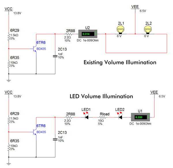
|
|
-
-
sonavor
- Joined on 02-13-2011
- Texas
- Posts 193
|
Re: Beomaster 6000 Refurbish
On the frequency signal, I pulled the IC8 from the socket and checked for the signal on the IC8 pin 2 location of the socket and I'm not seeing anything there. Hopefully this new IC8 is still good.
|
|
-
-
sonavor
- Joined on 02-13-2011
- Texas
- Posts 193
|
Re: Beomaster 6000 Refurbish
I created a couple of led lamp substitutes for the volume lamps. I had four clear/white LEDs to make two assemblies. I'm not happy with the result though. The light is too dim. The LEDs are ROHM SLA560WBC7T2 with a forward voltage of 3.2V (@20ma) and a typical brightness of 1000mcd. The picture here is the first attempt. It used a load resistor of 100 ohms. In the second try I used 22 ohms. The picture of the display was with the 22 ohm load resistor and the two ROHM LEDs. At least I can see that the volume control light circuit works. I'll have to look for some 6V, 1W lamps.
The display in the picture also shows the 74.8 frequency in the display. I currently have the IC8 frequency pre-scaler chip out of the socket. I was measuring pin2 of the socket to see if the tuner board was sending anything and I am getting zero volts, zero frequency.
So far the unit has still been solid in staying on and in the selected program mode. The frequency display and volume level illumination are all that is left I think. 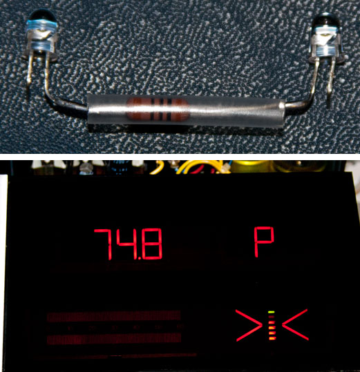
|
|
-
-
Step1
- Joined on 07-06-2008
- Manchester
- Posts 961
|
Re: Beomaster 6000 Refurbish
Something very wrong there! I got the brightness right by using my
adjustable powersupply with leds and ameter in situ then used the
forumla (Vs - 2xVf) / If Vs=supply Vf = led forward voltage If = forward
current.
The leds I use are ultra high brightness types that I purchased specially. However, Martin has a stock of bulbs so try contacting him if you don't want the hastle of messing around!
http://i170.photobucket.com/albums/u270/olly-k/Img_5627.jpg
This was when I was messing with various resistors. can't remember the value I settled on but the above method / formula is how I did it without difficulty.
Regarding the reset proceedure yes it involves removing the supply plug and injecting about 4.6V(?) into the reset circuit and adjusting Vd over a resistor to some value I can't remember atm. Should be along side no load proceedure etc. in your manual.
|
|
-
-
sonavor
- Joined on 02-13-2011
- Texas
- Posts 193
|
Re: Beomaster 6000 Refurbish
I think the LEDs are probably the issue here. I only had the clear ones I tried and some yellow ones. The LEDs I tried don't radiate the light very well. They are very bright directly out the front. I tried filing down the tops to difuse the light out more but I didn't notice any difference. I forgot to mention that I tried the two LEDs on a breadboard first with a trimmer and a DC power supply set to the 6.5V as the Beomaster 6000 circuit has. I'm not sure I want to spend too much time on experimentation with this. I think I will check with Dillen for bulbs as you suggested.
The top issue right now is the frequency display. With the IC8 pre-scaler removed on the 02 board I should be able to see the signal from the tuner board - the pin 2 measurement point in the diagram here, right? I am not getting anything at that point at all. 
|
|
-
-
sonavor
- Joined on 02-13-2011
- Texas
- Posts 193
|
Re: Beomaster 6000 Refurbish
To rule out a faulty cable or connection between the tuner board and the microcomputer board I checked continuity between P26-1,2 and P7-2,1. I also disconnected the P26 connector from the tuner board and used a frequency generator to send signals through the cable to make sure I could measure them okay on the IC8 socket pin 2...which I could. That means something broke down on the tuner board (08 Module) since nothing comes out of P26-1 when the tuner is operating. When I had first had the Beomaster working (kind of) after fixing the 6.5V power supply problem I was seeing the FM tuner display working. Shortly after that the display was randomly jumping around. I have been thinking that was related to the reset problem but maybe it was just the current problem in its early stages.
Here is the portion of the schematic on the 08 FM Tuner board where the FM frequency monitoring for the display comes from. The signal comes from circuitry inside the metal box. I might have to un-solder that to check the transistor (8TR2) in there. No trim pot to be a prime suspect here. The 8TR2 circuit just taps off the 8L2 transformer. I measure the voltage on either side of the 8R12 resistor as shown in the picture. Since I am able to tune and listen to FM stations just fine I am thinking the problem is in the 8TR2 circuit - either 8TR2, 8C7 or 8L1. 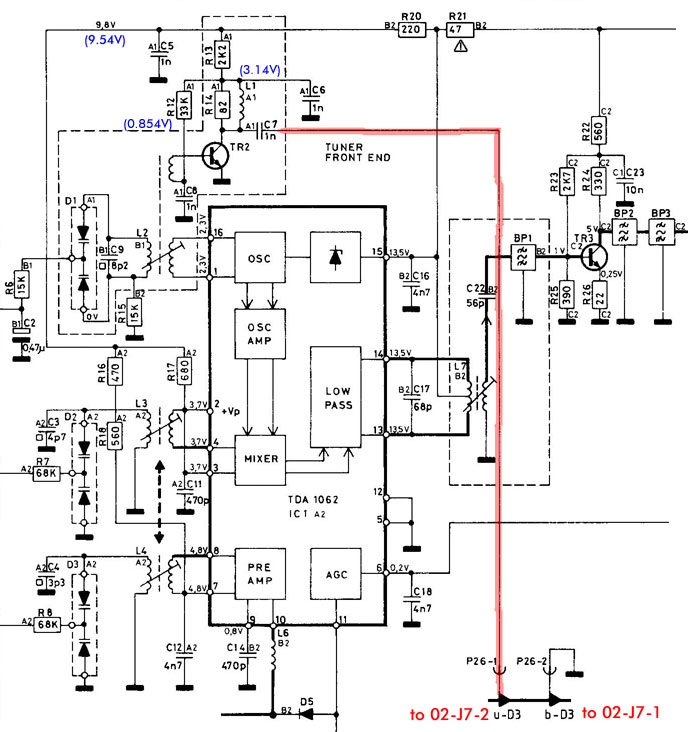
|
|
-
-
-
sonavor
- Joined on 02-13-2011
- Texas
- Posts 193
|
Re: Beomaster 6000 Refurbish
But if there was a signal on that line wouldn't I see it at the measurment point in the previous picture - IC8 socket pin 2? At that point the scope probe shouldn't affect it I wouldn't think since there is 2R66 (82 ohm) load across 2L14. I tested a signal going through to that point with a frequency generator (2MHz signal) and read it with the scope with no problem.
|
|
|
|
|