|
Untitled Page
ARCHIVED FORUM -- April 2007 to March 2012
READ ONLY FORUM
This is the first Archived Forum which was active between 17th April 2007 and
1st March February 2012
Latest post 02-20-2012 4:42 PM by sonavor. 215 replies.
-
-
 chartz
 
 - Joined on 07-20-2009
- Burgundy
- Posts 984

|
Re: Beomaster 6000 Refurbish
Tell us, how do you like your MC120.2, compared to the Redlines?
I've always wanted a pair of RL140/2000, and I have been wondering about their sound quality.
|
|
-
-
-
tournedos
  - Joined on 12-08-2007
- Finland
- Posts 5,808
|
Re: Beomaster 6000 Refurbish
 Step1: Step1:
If you have a sensitve enough ammeter, you could try sinking and sourcing pin 38 from supply and ground respectively (directly on the processor) and see how much current the pin is pulling?? I would think this would give you an instant indication as to where to look next!
...but use a series resistor and the CPU powered up! We don't want to kill it with an unlucky latch-up condition if some connection isn't OK...
Anyway, it might be enlightening to repeat the test with that input driven directly from a signal generator, but put some 1k resistor in series and watch the signal levels on both sides of it. That would tell the dynamic currents in & out. And please keep the scope in DC setting when looking at logic signals, the absolute H & L voltage levels referenced to ground are far more interesting than relative amplitudes the AC mode is showing.
But I agree the best thing to do right now is have a break. You get blind to the simplest things when you battle with the same problem for days on end.
And nice speakers 
|
|
-
-
Stonk
  - Joined on 04-16-2007
- Marlow, Bucks, UK
- Posts 1,688

|
Re: Beomaster 6000 Refurbish
An astonishing collective of electronic knowledge/wizardry here.
From a person who's had some success by just hitting the thing in various places until it works again - if you need any help on that front, I'm your man In the meantime I shall continue to watch this thread in awe. In the meantime I shall continue to watch this thread in awe.
If you think nobody cares, try missing a couple of payments.
|
|
-
-
sonavor
  - Joined on 02-13-2011
- Texas
- Posts 193

|
Re: Beomaster 6000 Refurbish
It's difficult for me to compare speakers to each other Jacques. In accumulating a number of different brands and models of good speakers I find myself enjoying each one. From time to time I have set up several pairs and switched between them trying to do my own comparison but I always end up undecided and enjoying the music. Today was the first time listening to the MC120.2 speakers and I am impressed with them. They sound tight and clear. I did try a quick listening test between them and the RL140's but for me it was a wash. The RL140's might have a broader sound stage. One thing about the RL140's is they are large. For that reason I was more impressed by the sound of the RL60.2 speakers. They are much smaller and have a pretty big sound. One of my favorite combination of B&O speakers though are the S45.2's and the S75's. I think they sound really well together. I plan to do a lot more listening to the MC120.2 speakers the next few weeks so I'll know more about them as I play different kinds of music on them.
Sonavor
|
|
-
-
sonavor
- Joined on 02-13-2011
- Texas
- Posts 193
|
Re: Beomaster 6000 Refurbish
Thanks Mika and Olly. That sounds like a good test. I am going to take a little break and just listen to some of these speakers through the Beomaster 6000...continuing the break in test of the new electrolytics and enjoying the sound at the same time. After all, enjoying the sound is a primary goal in all of this.
Sonavor
|
|
-
-
Søren Mexico

- Joined on 09-13-2007
- Mexico city
- Posts 1,621
|
Re: Beomaster 6000 Refurbish
Also changing between amps gives you a different sound, it doesn't get worse or better, but different, and as John I end up just enjoying the music
Beosound 3000, BL 4000, BL 8000, BG 2404,BG 5000, BG CD50, Beocord 5000, BM 901, BM 2400, BM 4000, BV S45, BV 3702. There is nothing we cannot do, but a lot of things we don't want to do!!
|
|
-
-
sonavor
- Joined on 02-13-2011
- Texas
- Posts 193
|
Re: Beomaster 6000 Refurbish
Ready to continue.
The volume display lamps from Dillen arrived earlier in the week. While on break from the Beomaster 6000 I've been busy at work and I did a restoration on another vintage piece (a non-B&O piece ...so please, no offense to anyone here).
This weekend I plan to install the new lamps and button up the display portion of the Beomaster. I will also attempt the signal test again to the IC4 pin 38 - directly from my signal generator, through a 1K ohm resistor.
-Sonavor
|
|
-
-
sonavor
- Joined on 02-13-2011
- Texas
- Posts 193
|
Re: Beomaster 6000 Refurbish
Here is a picture of the test setup and results.
I disconnected the white wire that carries the mod board flip flop output (with the scaled tuner frequency) to the IC4 processor pin 38. I soldered a 1k ohm resistor to the white wire and connected my scope probes on either side. Next, I connected the low side of my ammeter to the end of the 1k resistor and the positive side to my signal generator. Ground for everything was the Beomaster 6000 ground. I set the signal generator to output a TTL/CMOS level square wave then turned the Beomaster on (and to the tuner). I varied the signal generator frequency and saw that the Beomaster 6000 display moved with it. The oscilloscope showed that the clock signal was steady and stayed at a solid peak-to-peak voltage. The side of the resistor to the IC4 processor actually looked cleaner. There was a one volt drop across the 1k resistor. The ammeter showed that the current was a constant 0.001A. I also increased signal generator frequency so that all of the digits displayed on the display (106.3). 
|
|
-
-
tournedos
- Joined on 12-08-2007
- Finland
- Posts 5,808
|
Re: Beomaster 6000 Refurbish
Good, now we know that 1 mA of drive current will be enough for the CPU input, but for some (unfathomable to me) reason the divider circuit can't supply it. If that will be the last obstacle between getting this CPU module to work or acquiring a new one, we can build a buffer stage in between.
But, that will all be useless work if the signal doesn't come from the tuner board in the first place. If you can get the tuner to actually tune to a station - I think you said earlier that you could - the intermediate frequencies in the divider chain (the input for the problematic LS74, for example) need to be there and stay there even after the receiver warms up.
|
|
-
-
sonavor
- Joined on 02-13-2011
- Texas
- Posts 193
|
Re: Beomaster 6000 Refurbish
I forgot to mention that I also left the TTL/CMOS signal generator on for over an hour and the display did not freeze up. It still moves when I change the frequency of the square wave. Back when I tried the higher output flip-flop the display worked for a while, then eventually stopped working.
I agree with Mika about needing to get a signal coming from the tuner board.
Reviewing the problem from the tuner board -
At one point, when I first substituted in the new scaler chip (IC8), I read a valid FM channel on the display. It was correct because I knew the station I was tuned to. A minute or two later the display jumped around and froze. So the clock drive problem has been there a while I think.
After going through the whole power supply adjustment problem (not having the trim pots adjusted after the recap), I started having the IC4 "P" problem. Once that was sorted out I had a working Beomaster 6000 but it now was back with the stuck FM display problem (74.8).
As I investigated the scaler and clocking circuit I wasn't seeing anything from the tuner board. I also threw myself off course a bit during that because I wasn't thinking about my scope only being a 25MHz oscilloscope when I checked the signal directly from the tuner board. That mistake led me to messing with the tuner board and screwing up the FM tuning. However, even though the tuner board isn't working perfectly, it can tune some stations so it should be sending some sort of signal to the processor board.
Realizing I cannot directly measure the FM signal from the tuner board I now rely on measuring the scaled clock signal that is derived from the FM signal. That is the flop flop and clock divider ICs. Those I can measure. The IC8 prescaler scales down the FM signal frequency by 1/64. The remainder of the clock counters and flip-flop divide by another 8 (for a total of 512).
On those devices I am not getting anything from the tuner board. As a check of those devices working I can substitue and FM signal from an FM signal generator (through the cable from the tuner board to the processor board). Using that method I can see the scaler, dividers and flop-flop working.
That gets to the point I am currently at. Using the FM signal generator I can measure the scaled and divided clock signal going from the flip-flop to the processor frequency measurement pin (IC4 pin 38). It works when the the unit is first turned on, then stops because the flip-flop output cannot drive the signal low enough for a good TTL clock signal.
In the previous test, I cut the connection from the flip-flop to the processor and substituted a TTL clock from a signal generator (through a 1k ohm resistor). It is able to drive the processor measuring system without any drive problems and the current through the 1k ohm resistor didn't go over 1mA.
Today, I decided to try another test. I kept the clock source for the processor frequency measurement (IC4 pin 38) as the TTL/CMOS signal generator. I also used the FM signal generator to send an 80MHz FM signal to the scaler/divider circuit and monitor the flip-flop output. I measured that the scaler/divider transformed the 80MHz FM signal to a 156.3KHz clock signal. So I set the frequency of the TTL square wave as close to that as I could (155.4KHz - the fine adjustment on my generator is hard to lock in). You can see in the picture that the Beomaster is displaying 68.8. I expected it to be around 80. In an earlier test I was observing the same scaling and dividing. As I mentioned earlier, the IC8 prescaler scales the FM signal by 1/64. The clocking divider circuit then divides it by 8. So in my latest test 80MHz x 1/64 divided by 8 = 156.25KHz which is what I was seeing at the flip-flop output. I can't believe the processor would become inaccurate in measuring the TTL clock. I would think it either could measure it or not...when it can't measure it is when it just displays 74.8. 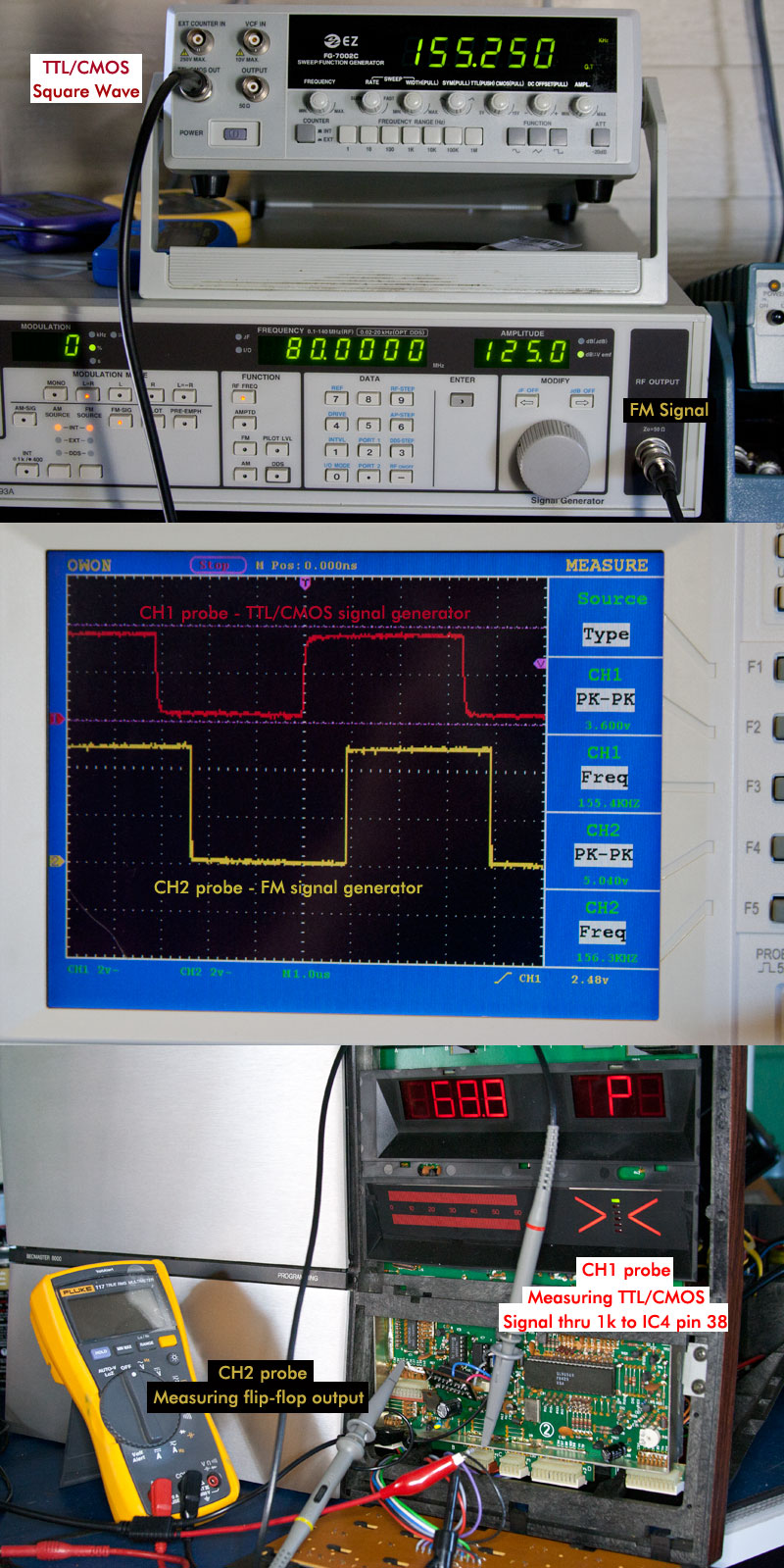
|
|
-
-
-
sonavor
- Joined on 02-13-2011
- Texas
- Posts 193
|
Re: Beomaster 6000 Refurbish
Well, this is kind of interesting.
While I had the test setup with the signal generators, the ammeter, oscilloscope, 1k ohm resistor and the flip-flop to IC4 pin 38 wire opened up, I decided to see what happens if I removed the TTL/CMOS signal generator (which as been driving the IC4 pin 38 through the 1k ohm resistor) and in place of that signal generator - re-connect the flip-flop output through my ammeter.
So I have the FM signal generator sending a valid FM signal into the 02 Module as if it were the tuner board. That FM signal is being pre-scaled and divided, then sent out through the flip-flop (currently a TI CD74HCT74E). The output of the flip-flop normally goes directly to IC4 pin 38. In this test it goes to the positive lead of my ammeter. The negative lead of the ammeter takes the signal to one side of the 1k ohm resistor. The other side of the resistor goes to IC4 pin 38.
With that test setup in place I turned on power to all of the pieces. I have my two scope probes on either side of the 1k ohm resistor.
When I vary the FM signal frequency I am seeing the Beomaster 6000 frequency display change. The value is still off but it is tracking. The oscilloscope shows a solid clock signal on both sides of the resistor. My ammeter toggles between 0.001 and 0.000. The difference between the two scope voltage measurements across the resistor looks really small.
I have seen the Beomaster frequency display track my FM signal generator on previous tests. But after a short bit, the display would freeze. So far, after about an hour, it is still working. The difference right now between this test of using the signal generator and monitoring the flip-flop clock (and display) is that I am routing the signal through an ammeter and 1k ohm resistor. I guess the next test is to remove the ammeter and see if the the display continues to work.
About the display value being off...Since I don't have the capability of measuring a real signal from the tuner board to the pre-scaler, I wonder if there is some offset of the frequency before the signal leaves the tuner board. In other words, is my test of applying frequency X at the connector from the tuner board and expecting the value of X on the display valid? What I am seeing is the Beomaster display about 7MHz lower than what I am sending (I set the FM signal to 80MHz and the Beomaster shows 73.3). That in itself is a little weird since the flip-flop output frequency for the 80MHz FM signal is now coming through as 163.4KHz (versus 156.25KHz). I thought that maybe 80MHz isn't really valid so in ran the FM signal up through 108MHz. The Beomaster display remained around 7 to 8 MHz off through out. 
|
|
-
-
sonavor
- Joined on 02-13-2011
- Texas
- Posts 193
|
Re: Beomaster 6000 Refurbish
I made another discovery. In thinking about how I am substituting the Beomaster tuner board FM reference to the 02 Module prescaler (so it can prepare the signal for measurement), I really have no idea what the Beomaster is expecting in terms of amplitude and load. I removed the ammeter from the circuit and have the flip-flop output now going to the 1k ohm resistor, then to IC4 pin 38. With power back on the test results are the same as the previous post picture.
Now I started to adjust the amplitude of the FM signal generator. Sure enough, as I lowered it the frequency of the flip-flop output signal changed. I was able to find a signal generator output setting that allows the Beomaster display to match the frequency on. I am going to let that run for a while. My next step will be to remove the FM signal generator and reconnect the Beomaster tuner board reference signal.
|
|
-
-
sonavor
- Joined on 02-13-2011
- Texas
- Posts 193
|
Re: Beomaster 6000 Refurbish
I performed the next step....and I might be back in business.
One thing you can see on the previous postings with the oscilloscope pictures is that the scope probe on the side of the 1k resistor that goes to the IC4 pin 38 is cleaner than the scope probe between the 1k resistor and the flip-flop output. I have both probes set to X10 range so they should have less impact on the signal. So is the 1k ohm resistor in series with the flip-flop output and the IC4 pin 38 input doing something? Also I should note that the flip-flop I am using is one of the new, higher drive flip-flops (TI CD74HCT74E).
So this current test was to remove the FM signal generator and return to using the FM reference signal from the Beomaster 6000 board. It appears to work! I am now back to turning the Beomaster tuning wheel and seeing the output on the display.
It is not a complete success yet however. I need to let this run for a while and make sure the display doesn't freeze. After that I will need to run it with the oscilloscope probes removed to see if just the 1k ohm resistor allows the circuit to work. If it does then I will be left with the task of fixing my screw-up of the tuner board. Right now I can tune stations and hear enough to know I am on the right frequency. The problem is there is low rumbling and interference from something. But if I have a display working I should be able to start going through the service manual adjustment procedures for the tuner. I just hope I didn't damage an inductor or some delicate tuner part.
|
|
-
-
sonavor
- Joined on 02-13-2011
- Texas
- Posts 193
|
Re: Beomaster 6000 Refurbish
Tuner performance is much improved!
I tried to retrace my steps back when I messed with the tuner board. What I had tried to do back then was verify the 08TR2 transistor and see if I could measure the FM reference signal from that circuit. Of course I realize now that was dumb because there wasn't anyway my 25MHz scope would see anything and even if I had a higher range scope, the probes would likely have interfered with the signal.
I ended up desoldering and measuring 08TR2 and 08D1. Both had meausured okay. In the process though I had accidently de-soldered 08L1 and 08R14. Those two schematic reference designators are actually one component - listed in the parts list as L1/R14 (Coil). When I put the components back together I had wondered if I replaced that coil correctly. Since they are inside a metal casing I had no picture of them prior to removal. Since then, the tuner hasn't worked properly.
Tonight I decided to remove the 08 board and the metal cover over 08TR2 (and L1/R14). I de-soldered L1/R14, reversed it and soldered it back in place. Then I soldered the metal cover and re-installed the 08 module.
Now the FM tuner appears to be working again. Stations are clear and the display is showing the correct frequency.
Next step is to re-arrange the 1k ohm resistor from the mod PCB to the IC4 pin 38 (on the 02 Module) so the cover can be put back on ... and the display still work. 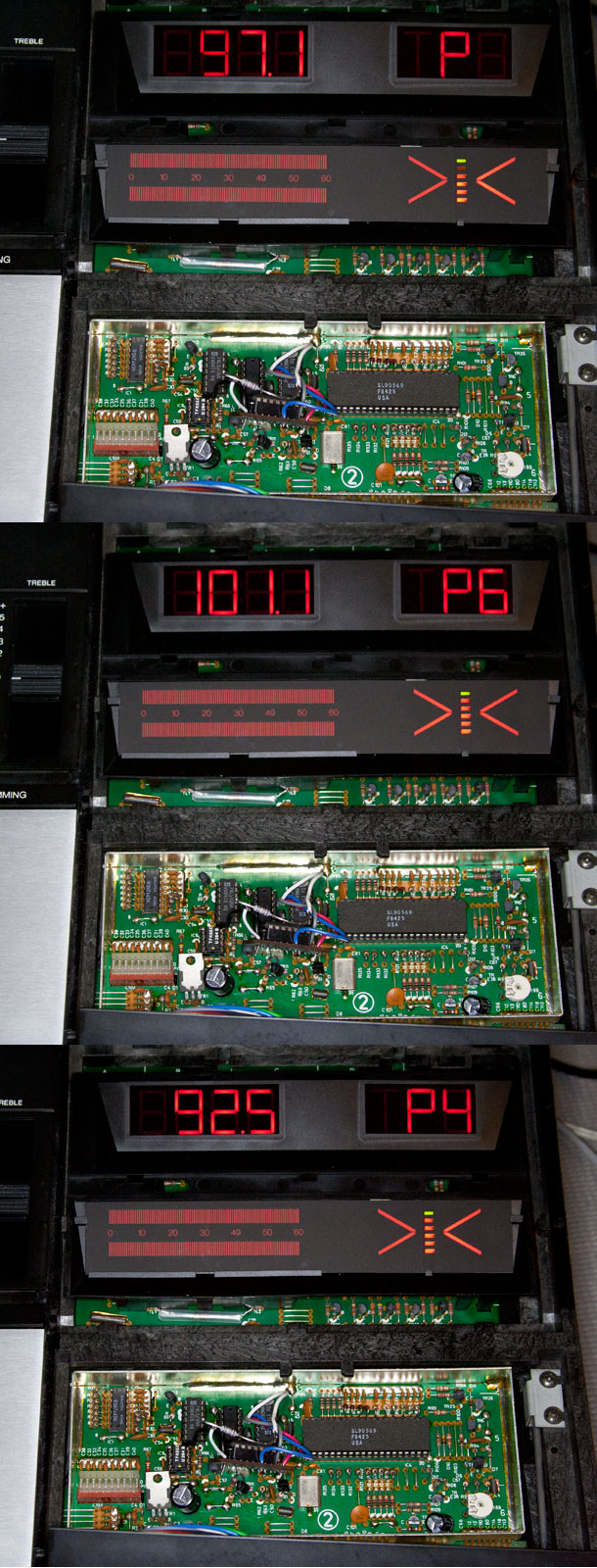
|
|
-
-
tournedos
- Joined on 12-08-2007
- Finland
- Posts 5,808
|
Re: Beomaster 6000 Refurbish
For now, I just skimmed over your latest posts as the last one seemed to show some success already 
The reason you were not seeing the frequencies you expected is that the signal coming from the tuner to the divider is not the frequency it is tuned to. It is the local oscillator frequency, which is 10.7 MHz off. In an FM tuner, it is mixed with the incoming RF signal to produce a subtraction result, where the desired station is at an intermediate frequency fixed at 10.7 MHz.
The IF signal goes through a chain of bandbass filters to remove all other frequencies, and then onto an FM detector which finally outputs baseband audio (still modulated with some funny stuff to cater for stereo, but let's not get into that ).
|
|
-
-
-
sonavor
- Joined on 02-13-2011
- Texas
- Posts 193
|
Re: Beomaster 6000 Refurbish
So you are wanting me to try something like a 100 ohm resistor in parallel with the 1k or replace the 1k with a 100 ohms and check that result? I guess now would be the opportunity to do that.
I think this Beomaster is going to insist I go through every type of adjustment on this project. After I lowered the lid and have just the area of the 02 Module exposed where I can measure the series resistor and monitor the FM display, the volume motor stopped working. I tilted the lid back up and checked for loose connectors but everything is still tight. It also isn't an issue with the keypad. I have had the volume preset at zero so when I turn the Beomaster on/off the motor has been resetting to zero. Now it is not. I should be getting used to this now but I was really looking forward to wrapping this up.
|
|
-
-
-
tournedos
- Joined on 12-08-2007
- Finland
- Posts 5,808
|
Re: Beomaster 6000 Refurbish
sonavor: So you are wanting me to try something like a 100 ohm resistor in parallel with the 1k or replace the 1k with a 100 ohms and check that result? I guess now would be the opportunity to do that.
That's effectively pretty much the same thing - but the only purpose of that resistor was to turn AC current into voltages so it was possible to observe the current with a scope. No need to have it there at all if the counting works without it. But now that we are onto something, don't alter more than one thing at a time!
|
|
-
-
sonavor
- Joined on 02-13-2011
- Texas
- Posts 193
|
Re: Beomaster 6000 Refurbish
I agree. I don't want to rock the boat. The 74 flip-flop that is in there right now is the last one I had tried before when the display was not working. So adding the resistor did something it likes. The only visual thing I can see is that it interacts with what is already there and the IC4 side of the resistor has a clean, square signal. If you look at one of the oscilloscope pictures where I show the signal on either side of the resistor you can see large spikes on the CH1 (red) probe measurement. I wonder if those were causing problems with the IC4 reading the value.
I was checking out the tuner (and presets) some more today. The tuner still isn't 100%. I am getting some drift and frequency hopping. It is like the tuner can't stay locked on to the station. Maybe the problem was there last night but there is more interference during the day? So I will have to try and run some of the service manual tuner checks. Having not done that before - I've read where you have to be careful and use a non-ferrous screw driver. Is that right?
|
|
-
-
tournedos
- Joined on 12-08-2007
- Finland
- Posts 5,808
|
Re: Beomaster 6000 Refurbish
sonavor: The 74 flip-flop that is in there right now is
the last one I had tried before when the display was not
working.
If you mean the HCT type (which stands for
"high-speed CMOS, TTL compatible"), it is faster than the original pure
TTL chip from the LS family. This means that the rise & fall times
of the digital signals are much shorter than with the original chip, and
that can manifest itself as those under- and overshoot spikes you see
in the scope picture. It is possible that they aren't read cleanly by
the CPU input pin, and having the resistor in series smooths them out
(it will work as a low pass filter in combination with the input
capacitance of the CPU pin).
I guess I'll change my advice on that to leave it there if it works
If
you are going to touch the coils in the tuner (I don't recommend it -
they haven't been turning themselves around just to annoy you!), you
will indeed need a non-ferrous adjustment tool. Part of that is that
inserting something ferric into the coil will alter its tuning and
you'll have no idea of what is happening while it is in there. The other
part is that the coil cores are made of ferrite particles pressed
together with some bonding material, and they will crack very easily if
you put any force on them with a sharp, hard tool.
|
|
-
-
sonavor
- Joined on 02-13-2011
- Texas
- Posts 193
|
Re: Beomaster 6000 Refurbish
Okay. My plan now is to first trouble-shoot the volume control problem that popped up. I have to have that working. Once that is solved I think I will run through the tuner checks described in the service manual.
|
|
-
-
sonavor
- Joined on 02-13-2011
- Texas
- Posts 193
|
Re: Beomaster 6000 Refurbish
I've been tied up with other things this week and finally got a chance to look at the Beomaster 6000 volume problem tonight. In the attached picture I have put the related schematic pieces for the volume control. To the right is a table of step and voltages from the service manual that show the approximate voltage levels for each step of the volume setting buttons on the keypad (0, 10, 20, 30, 40, 50 and 60). The measurement point is the cathode of diode D8 as I show with the read line and arrowhead. When I press those volume buttons I measured those voltages so that was good. It means the IC4 is reading the correct keypad switch and the volume select chip sets the right voltage. Unfortunately the motor doesn't move at all. Earlier I had monitored the volume select up arrow and down arrow volume signals at 6R36 and 6R37 and saw that those changed when I pressed the up and down buttons on the keypad. So the control signals are arriving at the volume select and appear to be doing what they are supposed to. Next I measured test points TP20 and TP21 on the 05 Module (the volume motor). When I apply AC power to the Beomaster the TP20 side measures about 1.45 VDC and the TP21 side measures 14.13 VDC (both with respect to ground). When I press any of the volume control buttons that should raise the voltage the voltages reverse to TP20 having 13.56 VDC and TP21 having 1.56 VDC. Since the motor doesn't move, those voltages remain at that state.
So maybe the motor died?
This Beomaster has really done some odd things though. The volume motor, 03 Module (preset control, tone control, tuner) hasn't been touched since the recap. But maybe something failed there and I am getting some kind of interference? I have been noticing that when the Beomaster is first turned on (cold) the tuner seems to work pretty decent and shows the correct station frequency in the display. After a bit it will jump. I was thinking that problem was because of my 04 Module (tuner board). However, tonight, when I was doing the measurement of the volume motor test points I saw the tuner change as I pressed the up and down volume control buttons !!!!!
How and why did that develop? Remember that for a while I didn't use the Beomaster tuner at all and I just used it as an amplifier. The volume control worked fine at that point. So to go from that to where the volume buttons interfere with the FM tuning and the volume motor doesn't work is baffling to me. I am going back to plan B which is wait for a parts unit Beomaster to surface so I can have something to compare with. It was very helpful having a parts unit on the Beomaster 4000 project.
-Sonavor 
|
|
|
|
|