|
Untitled Page
ARCHIVED FORUM -- April 2007 to March 2012
READ ONLY FORUM
This is the first Archived Forum which was active between 17th April 2007 and
1st March February 2012
Latest post 11-19-2011 9:38 AM by Step1. 81 replies.
-
-
 Eugene
  - Joined on 12-17-2008
- Posts 589

|
 geearr: geearr:
Thanks Eugene
Pleased to hear that you are watching - I can always do with some help from someone with your experience. Have you worked on the "quad" before? If you answer "yes", be careful because you will be inundated with a stack of questions.
Regards
Geoff
No Geoff I have not worked on a quad before and considering all the time and patience needed to restore one of those beasts experience tells me to stay away. I do like the innovations you used to put it all back together. A lot of fiddly tweaky reassembly.
Interesting that you used the "tapping" method to find fault on the tone control board. Done that myself a few times on the Beomaster 2400 tone controsl. Not very technical or scientific diagnostic but it sure beats the hell out of dragging out the sillyscope and soldering up test lead and all that time consuming business to isolate one small component failure.
Now that you have her running again I suppose its time to sit back and enjoy the sound for a bit.......
but at some point are you going to open her back up and replace all the reamining original electrolytic capacitors ?
|
|
-
-
geearr
  - Joined on 03-27-2008
- Gold Coast, Australia
- Posts 301

|
Hi Everyone
As I mentioned yesterday, this project is nearing completion. The Beomaster 6000 quad has now been re-assembled and will be put to one side while I catch up on all the other tasks that I have ignored over the last few weeks. So what are my latest conclusions about the “quad”?
Well, I have taken an old unit that wasn’t even making a noise and returned it to a condition where all four channels are producing a good sound. For me, that was the primary objective of all this work and I have achieved what I set out to do. Very satisfying for a rank amateur.
I have learnt that this Beomaster is extremely complex and difficult to work on. While trying to cram everything inside that tight box, I was always concerned about possible short circuits. Every time that I switched it on, I was expecting a flash of some sort. It will actually be a welcome relief to work on something easier for a change and see my pulse rate slow down.
It has been slow and painstaking work and I can understand why Martin inferred that there wouldn’t be too many people who would be prepared to undertake this assignment. The man hours are going to be very high and at times, progress is very slow indeed. I’d hate to be paying for it by the hour!
I have always liked the appearance and design of this Beomaster when I have seen it in the sales brochures and magazines. However, in reality, those horrible wear patterns on the push panels and the aging marks on the black display panel do make it less attractive when you look at it closely. Recovering that wonderful, original pristine condition would be a mission impossible for me.
My first impressions on the sound quality was that I was happy with it. One day, I will set it up properly for ambiophonic reproduction and give it a good test but in the meantime, it still sounds good on my “low fidelity” work bench. I don’t think that I will ever be able to get a quad source to evaluate - but one never knows.
The first pass on this Beomaster has fixed a number of issues but there still remains more work to be done. So far, I have come up with the following list. Most of these tasks are fairly simple but there are some that I would appreciate more help with. Here they are:-
The “power on thud” must be fixed and I am still not certain which components I am going to have to replace. This is probably the area that I least understand and require most help. I plan to investigate it more thoroughly next time the machine is open.
The front / rear balance indication is not working but I do hear the motor turning. This probably means that there is a wiring loom jammed on top of the drive wheel. Should be very simple to sort this one out – after all it was working when the cover was off.
The tuning indicator is very far out, probably about 50mm from the correct position. I am not sure how it got in this situation but it is normally fairly easy to reposition the clip on the string.
Some of the push panels are not acting as good switches. I hope that it will be possible to improve the sensitivity of these, after all, only a delicate touch should be needed, not a high pressure thumb print!! Has anyone tried to address this problem on these push panels or any other similar machine that uses them?
P5 tuner is definitely broken but I wasn’t able to get any access to the trimpot. My first impression was that it was a sealed unit but I could be wrong. Can anyone advise me how to successfully dismantle this assembly, there are no clues at all in the service manual.
There are several pinholes in the black mask on the display panel which let light through and detract from the appearance. A touch of black paint on the underside should fix that up fairly easily.
The cabinet requires a lot more TLC to bring it back to a superb condition. This is just fiddly, time consuming work that can be done at any time – but in the end, it will be well worth it.
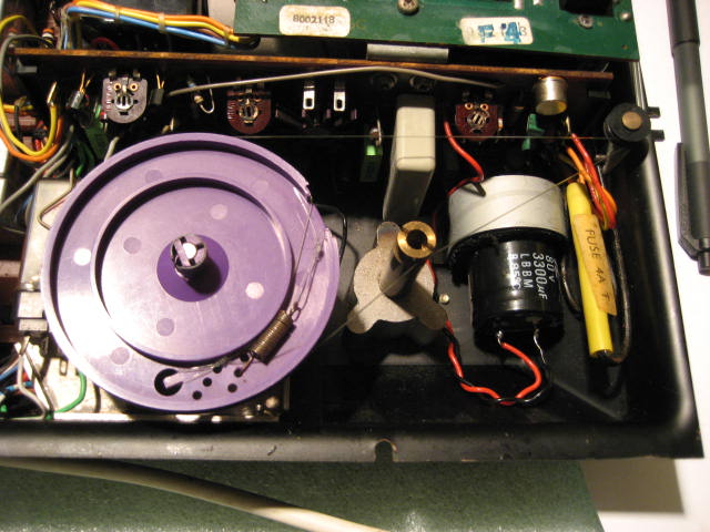
Well that is my short list, not much is it! This Beomaster is almost back to being a useful piece of audio equipment. Here it is ready to go into hibernation for a while.
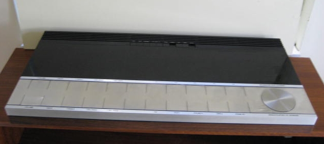
My thanks go to all Beoworlders who have been supportive of this project. I hope that you found it interesting and one day perhaps, this thread might be of use to someone else who is also working on the “quad”.
Best regards
Geoff
|
|
-
-
Eugene
- Joined on 12-17-2008
- Posts 589
|
Cant really see in detail the wear on the push panels, perhaps what I am looking at is 30+ years accumulation of oil dust dirt and grime, then add oxidation to the mix and your left with a dull dirty looking control panel.
If thats the case the good news is that it will all clean up nicely with the right soap and some patience and a bit of elbow grease. The tarnish can then be remove with a coat of brasso or similar metal polish.
The heavy top layers of surface grime will pull up quckly then it will be a matter of lifting out the deep ground in stuff. Repeated application of a suitable grease cutting detergent and a soft nylon bristle brush will do the trick.
|
|
-
-
geearr
- Joined on 03-27-2008
- Gold Coast, Australia
- Posts 301
|
Hi Eugene
Getting good photos of this machine has proved difficult for me but the photo below shows what we are up against.
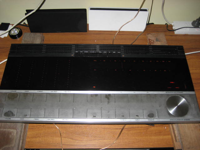
This was in the as-received condition with heavy wear on most of the popular keys. One of my first steps was to use the standard B&O cleaning recipe, ie water with one drop of washing liquid - applied on a damp cloth. All I can say is that only made things worse and all of the worn areas expanded dramatically. It looked as if there was a layer of lacquer that was peeling off and the more you rub it, the worse it gets. My only solution was to rub the whole lot off, back to fresh metal but I fear that the original factory finish has long gone by now.
Patience and elbow grease I have already used but now I will have to experiment to find a finish that is both durable and attractive. At the moment the keys do look quite nice but I am not sure how long that is going to last for.
Regards
Geoff
|
|
-
-
-
Step1
 
 - Joined on 07-06-2008
- Manchester
- Posts 961
|
I am not entirely sure these panels were anodised originally? I know it is brushed metal and there certainly is a layer of lacquer applied, which I would think means there is no other protection from tarnishing which anodising would surely perform!
@Geoff there have been threads where people have tried refinishing Beogram switch panels which are essentially the same as this model. Try searching if that helps! I have to do the same on a couple of Beograms but these are currently on the 'to do' list!
|
|
-
-
Søren Mexico
 
- Joined on 09-13-2007
- Mexico city
- Posts 1,621
|
Most Beo alu panels and buttons are anodized, what I have done is using this white 3M pad when polishing, using water poor or with detergent, it gives the nearly the same finish as the mate finish used in most parts, NOT very bright finishes, if I get down to the pure alu I go all the way until the whole surface is clean and even, then clean with acetone, use clean gloves, dont touch the clean surface with your fingers, emidiately after cleaning with acetone, spray 1 time with clear polyurethane, let dry and give it 1 or 2 more coats.
After cleaning with acetone the alu will start oxidizing, so its important to spray directly after cleaning.
Polishing, follow the structure like you do sanding wood.
Beosound 3000, BL 4000, BL 8000, BG 2404,BG 5000, BG CD50, Beocord 5000, BM 901, BM 2400, BM 4000, BV S45, BV 3702. There is nothing we cannot do, but a lot of things we don't want to do!!
|
|
-
-
geearr
- Joined on 03-27-2008
- Gold Coast, Australia
- Posts 301
|
Step1:
@Geoff there have been threads where people have tried refinishing Beogram switch panels which are essentially the same as this model. Try searching if that helps! I have to do the same on a couple of Beograms but these are currently on the 'to do' list!
Thanks Olly, I intend to read through all of the information that must be available somewhere. Likewise, this is going to take a low priority down towards the lower end of the "to do" list.
Regards
Geoff
|
|
-
-
geearr
- Joined on 03-27-2008
- Gold Coast, Australia
- Posts 301
|
Søren Mexico: if I get down to the pure alu I go all the way until the whole surface is clean and even, then clean with acetone, use clean gloves, dont touch the clean surface with your fingers, emidiately after cleaning with acetone, spray 1 time with clear polyurethane, let dry and give it 1 or 2 more coats.
Thanks Soren, I appreciate your ideas because those are the same lines that I have been thinking along - a good clean followed by a lacquer finish. That should work OK. The big hassle is going to be masking off the rest of the kit.
Regards
Geoff
|
|
-
-
burantek
  - Joined on 05-04-2007
- SE USA
- Posts 6,214

|
Thee BEST results on refinishing these keys I have ever seen: THIS THREAD.
The last post: Pebeo Vitrea 160 -available at arts/crafts type stores.
Also, scroll up a bit and follow the link to the Flickr pics -you will be amazed.
P.S. Just noticed the poster was looking for BM6000Q assistance!
|
|
-
-
Rich

- Joined on 07-10-2010
- Orlando, Florida, USA
- Posts 1,089
|
Well, this is probably going to be a n00b question. Are we talking about two separate phenomena here with the B&O metal finishes: (1) leaving oils (and other dirt and grime) behind from our fingers when we touch our equipment, and (2) an applied finish that will ultimately wear out no matter what precautions and cleaning we do?
When I look at my equipment, I can see where buttons have been pressed. I always thought I was seeing 1 above; have I been really seeing 2?
Current primary listening: SMMC20EN -> BG4002 -> BM4000 -> Beovox M70
|
|
-
-
-
geearr
- Joined on 03-27-2008
- Gold Coast, Australia
- Posts 301
|
Hi Everyone
I thought that I should provide an update to let you know how the finishing touches are progressing. As usual, the last 5% of any project always seems to take 50% of the time and this project is no exception.
I dismantled the Beomaster 6000 quad once again and can now claim to be able to do this in my sleep. One must wonder how many disassembly and reassembly routines these machines are designed to take? I am almost certain that some of my later problems are now a result of too much dismantling and this particular machine is always going to be very sensitive to that.
The first thing I noted was that one of the looms at the front had trapped the plastic wheel on the balance pot so that problem was fixed very easily. More care was simply needed when replacing the keyboard panel. One problem solved and six to go.
An easy problem to address was the alignment of the tuning indicator. I tuned in one of my favourite radio stations, switched the unit off and then placed the display panel on top. I measured the distance of the indicator from the correct mark and it was 49mm out.
The next step was to raise the tuning indicator and mark the desired position on the string with a black felt marker. Adjusting the indicator was fairly straightforward but you need to remember that when you want to shift the marker to the left on top, it must go to the right underneath. I messed that one up first time round. Two problems solved and five to go.
When I removed the black display panel, the pinholes were clearly evident and these had been produced where two surfaces were being pressed hard together. These I simply repaired using my faithful black marking pen and that worked very well. Three problems solved and four to go.
I next wanted to work on the tuning potentiometer. Here, I had been thinking along the lines that the pot itself was damaged but thought that I should first check the electrical aspects before wrecking the mechanical parts.
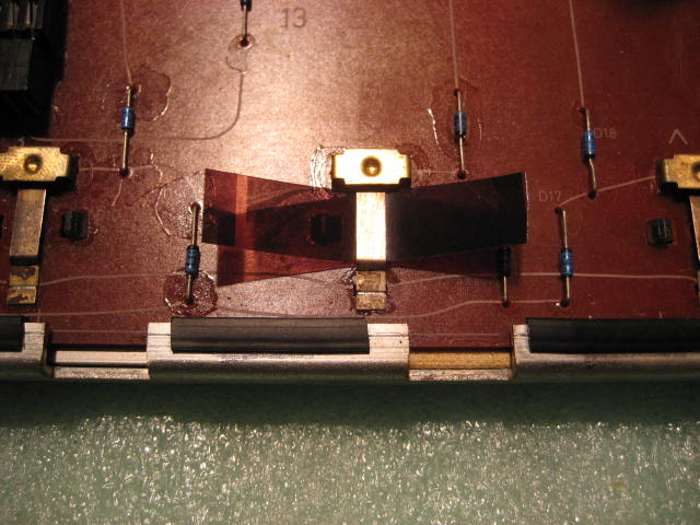
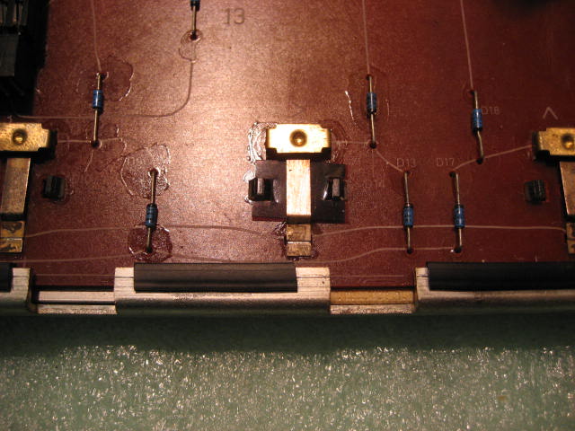
I studied the connections on the pre-set tuning board. There are five wires at the front that supply the switched high voltage to each tuning pot – Br/W, R/W, Or/W, Y/W, Gr/W. These should read 20+V when switched on and 0.5V when switched off.
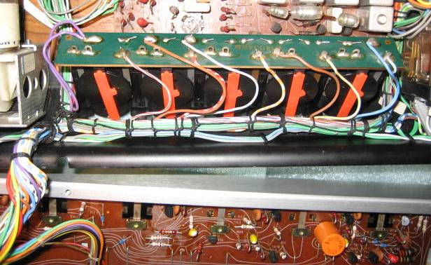
Each preset tuning pot has three connections. The left connection viewed from the front is the common low voltage to all pots. The centre connection is the tuner output voltage which goes through a diode to a common output (to PC2). The connection on the right is the switched high voltage connection.
When I switched in P5, it only recorded 5V on the high end. Since the low end was around 6V, the variable output was fixed at 5.9V and that is why the tuner stayed locked in one position. I next had to find out why the high voltage was so low.
The tuner voltages come from PC8 which underneath the keyboard, now conveniently parked at the front. When I measured the resistance from the Gr/W wire on the preset to the 8TR12 collector it was clear that there was no connection. I then traced the wire in the loom and found that it passed onto the underside of the board PC8. Fortunately, all of the wire connections are on the left hand edge where they are reasonably accessible. The wire had broken off on the underside of the board where it wasn’t readily visible. Resoldering that wire fixed the tuning problem.
Now, four problems have been solved and there are only three to go. Unfortunately, one does tend to leave the more difficult problems for last. I’ll report on those next time.
Regards
Geoff
|
|
-
-
Dillen
 - Joined on 02-14-2007
- Copenhagen / Denmark
- Posts 5,008
|
You will never run out of work with a Beomaster 6000/4.
Isn't it wonderful ? 
Thanks for taking the time to do this thread, it's great reading and will, no doubt, come in handy for many owners and DIY'ers.
Martin
|
|
-
-
Step1
- Joined on 07-06-2008
- Manchester
- Posts 961
|
I am consistantly impressed with your work Geoff. I think you will have a nice unit at the end of the day!
Regards the switch sensitivity issue, you need to unsolder the brass contacts that look like a goalposts - you should see these when looking at the component side of the switch pcb. Gently clean the tarnished contact surfaces and your switches should work like new again.
|
|
-
-
geearr
- Joined on 03-27-2008
- Gold Coast, Australia
- Posts 301
|
Hi everyone
I have definitely come to the conclusion that fixing a 6000 quad is not easy and there are pitfalls everywhere. On my last session, I wanted to lift the tuning indicator slide to access the amplifier board. I unscrewed it, lifted it and the string snapped for no apparent reason. It must have been chaffed and old in one area and decided to give up the ghost.
I really didn’t want to do that job but it had to be done and for starters, I have no spare string at all. So I decided to use the second best option that has worked for me in the past and that is 0.35mm fishing nylon. Not the best because it tends to be too elastic if the tension is not high but it is all that I have at the moment.
I normally hate doing these stringing jobs but for some reason, this one went fairly easily. The main requirement is to have an assistant with those two extra hands – one set is not enough. For those that might have to do this job in future, the following procedure worked well for me.
Remove all of the old string and measure the exact length if you can. I estimated that the distance between the tips of both knots was around 166cm.
Cut 2m of suitable line and knot a small loop at one end. This is sized to slip over the lug on the plastic wheel.
Install the plastic wheel on the tuning pot and turn fully anticlockwise.
Fold the line double and thread it up the tuning indicator and around the end pulley. The side with the loop has to be at the front. Use an elastic band to keep the line in place around the pulley. This is where the extra hands start to become necessary.
Position the looped end on the left front side of the capstan and wind two turns clockwise onto the capstan. Make sure the latest turn lies on top of the other.
Keeping the tension around the capstan, adjust the length of the looped end so that the line can be wrapped around the wheel and the loop located over the lug. Tension the line on the right side of the capstan and make sure that the line is located around the middle groove on the wheel. If you don’t keep the tension during the next steps it will fall off of the lug and you have to start again.
Pass the free end around the lower of the two front pulleys and the nearest pulley at the indicator. Next, remove the elastic band and pull it tight around the indicator end pulley. Pass the free end around the farthest pulley at the indicator.
Hold the free end firmly and start to wind the wheel clockwise. The coiling process should start half way down the plastic wheel and the line accumulates in the lower grooves.
When the wheel is fully clockwise, make sure that the free end of the line is around the correct pulleys and position it over the plastic wheel. Measure the distance for the loop that will be attached to the spring.
Make a small loop and fit the spring. Fix the spring to the wheel and ensure that the line comes out on the very top groove. Check that the spring has a bit of tension. If it hasn’t, you might have to relocate the spring to a different hole or re-knot the loop.
Turn the wheel anticlockwise to pull the line in on the top groove and it should feed out at the bottom at the same time. Test the full travel a few times and check that the tension is sufficient.
Find a favourite channel and set the indicator to the right position. I have marked this position with a small black dot on the plastic indicator. Slide the line over the retainer to lock the indicator ribbon in position. I used a piece of thin card (business card) to help guide the line over the retainer and pull it through.
2133
So, there we have the newly strung tuning system. It works and does the tuning job but I must try and source some of that proper tuning string one day. I haven’t had much luck in finding any to date.
Regards
Geoff
|
|
-
-
-
-
Eugene
- Joined on 12-17-2008
- Posts 589
|
Actually, just go fishing Geoff and make sure you take a cooler of beer with you. What has impressed me most is the thouroghness of the documentation regarding this restoration. very clear and well presented.
Using this thread as a guide many of us could now take one of these Quads when we would not have prevoius.
|
|
-
-
Step1
- Joined on 07-06-2008
- Manchester
- Posts 961
|
Eugene:
Actually, just go fishing Geoff and make sure you take a cooler of beer with you. What has impressed me most is the thouroghness of the documentation regarding this restoration. very clear and well presented.
Using this thread as a guide many of us could now take one of these Quads when we would not have prevoius.
Some good advice - especially regards the bear  I agree with the diary entries, I try, with best intentions to do a writeup and find it hard to set aside the time to take piccies and note descriptions etc... I get into to one flow or another! I agree with the diary entries, I try, with best intentions to do a writeup and find it hard to set aside the time to take piccies and note descriptions etc... I get into to one flow or another!
|
|
-
-
Søren Mexico
- Joined on 09-13-2007
- Mexico city
- Posts 1,621
|
Dillen:
You will never run out of work with a Beomaster 6000/4.
Isn't it wonderful ?
Thanks for taking the time to do this thread, it's great reading and will, no doubt, come in handy for many owners and DIY'ers.
Martin
I learn from every step
Beosound 3000, BL 4000, BL 8000, BG 2404,BG 5000, BG CD50, Beocord 5000, BM 901, BM 2400, BM 4000, BV S45, BV 3702. There is nothing we cannot do, but a lot of things we don't want to do!!
|
|
-
-
geearr
- Joined on 03-27-2008
- Gold Coast, Australia
- Posts 301
|
Hi Everyone
Thanks for all of the recent feedback, it has all been examined and I continue to find your comments very helpful and supportive.
The next phase was to try and improve the sensitivity of the keyboard because some of those switches were really hard work at times. The harder you have to press, the more damage you do to the keyboard appearance as well as putting a permanent kink in the key itself. Some of the switches were worse than others and it is no surprise to find out that the commonly used switches such as volume, stand by, FM and AUX2 were particularly bad.
Olly was right when he mentioned that the first thing to do is improve the contact surfaces. Each switch is made up of two parts. The first part is the copper bridge that is fixed to the PCB and the second part is the spring contact plate. I chose not to dismantle any of these parts and wanted to fix them in situ so as to avoid any unforeseen damage.
I decided to clean the contacts by cutting a thin strip of very fine emery paper and running this across both sides of the contacts. Afterwards, the switches were vacuumed and wiped over.
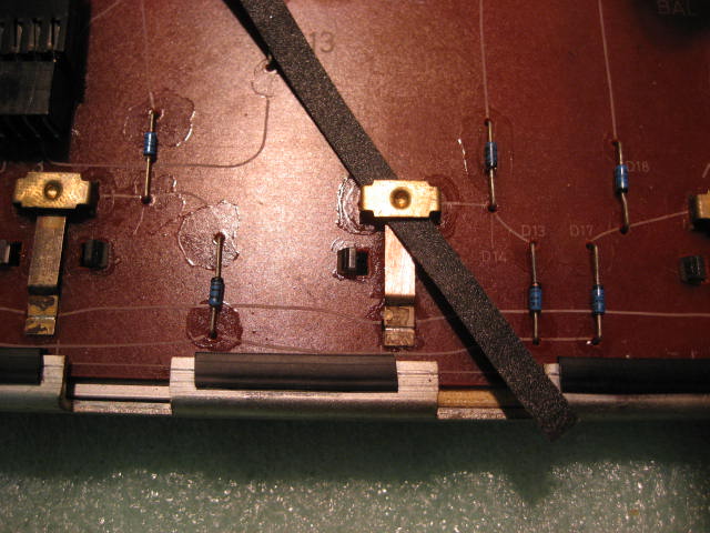
You can feel an improvement in the switching when the contacts are clean but it doesn’t provide a solution to how far the key has to be pressed. I used a small feeler gauge to test the gap in these switches. In the good switches, a 0.15mm gauge was just starting to find a snug fit. In the bad switches, this gauge just floated around all over the place and the gap could be more than 0.5mm. When I examined the different switches, I started to appreciate that the bridges were all the same but the spring plate had lost its shape in many cases. When I tried to bend these springs, nothing really happened. To be successful, one would probably have to remove the spring plates and reshape them externally.
I decided that the simplest solution was to make some shims to fit between the button at the back of the flexible key and the spring plate. I found some old photograph negative which was quite strong and about 0.25mm thick. A few layers of this would close up the gap significantly.
The dimensions of the shim are 10 x 15mm and on each side, a 4 x 4mm slot is cut around the centre. They don’t have to be that precise but should fit nicely over the two plastic lugs that support the switch.
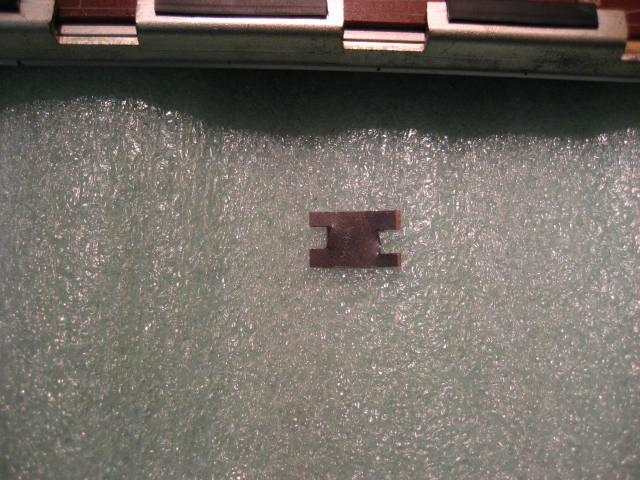
After these had been cut, I found that they were very difficult to slide into the switch and they would snag around the plastic button. The solution was to cut a strip of negative about 5mm x 50mm and used this to wiggle into place over the plastic push button. Next cut a strip 10mm x 50mm and slide this over the top. Then pull out the first strip. It is now easy to slide in the shims over the top of the strip.
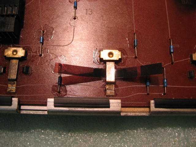
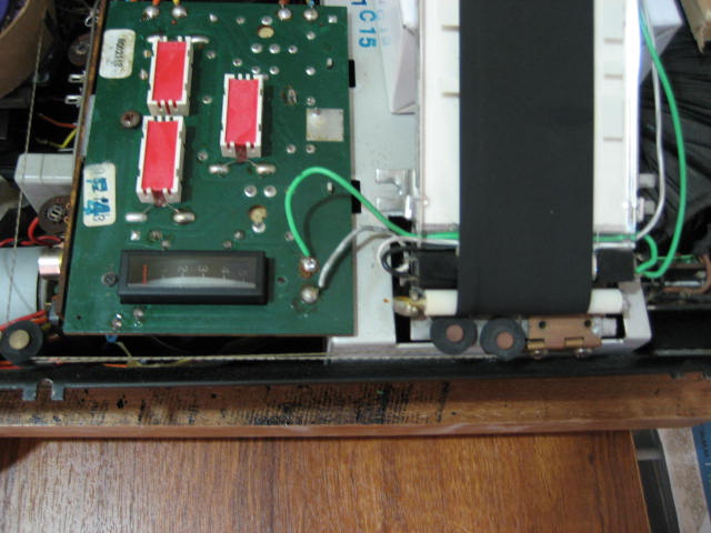
After putting in one shim, I connected a beep meter and pressed the switch to judge its sensitivity. In some cases, I had to put in three or four shims to make the switch acceptable. All switches now have a clearance of 0.10 to 0.15mm and the switching functionality has improved no end. This is a photo of the volume control panel with all of the shims in place.
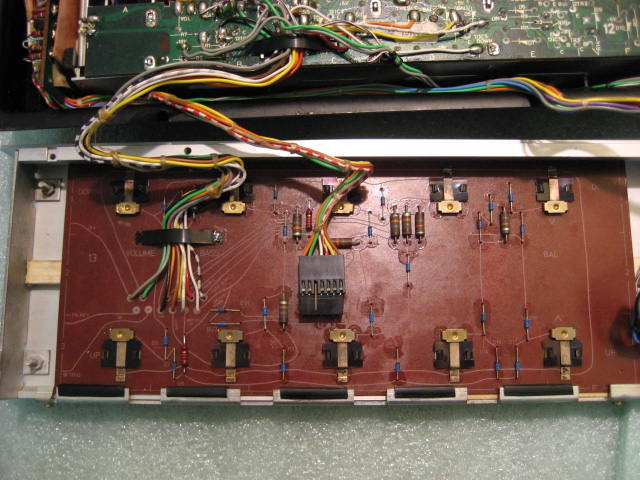
I am very satisfied with this solution. Five problems are now fixed and there are two to go. Some would say that it’s not quite a B&O replica but it doesn’t worry me when these parts are not visible to the user. The main objective remains to have a piece of equipment that is a pleasure to operate and ultimately a pleasure to listen to.
Regards
Geoff
|
|
-
-
Søren Mexico
- Joined on 09-13-2007
- Mexico city
- Posts 1,621
|
Beosound 3000, BL 4000, BL 8000, BG 2404,BG 5000, BG CD50, Beocord 5000, BM 901, BM 2400, BM 4000, BV S45, BV 3702. There is nothing we cannot do, but a lot of things we don't want to do!!
|
|
-
-
geearr
- Joined on 03-27-2008
- Gold Coast, Australia
- Posts 301
|
Hi Everyone
The latest update on the quad has both good news and bad news. First the good news.
After fixing the control panel, I reassembled the unit to give it a serious test run. The first problem I encountered was related to the improved key sensitivity because after the panel was pressed into position, program P1 was permanently engaged. Removing one of the shims under the P1 key quickly fixed that.
The control panel was now a pleasure to use – it was very sensitive and getting close to the touch panels on the BM2400. What a difference from the earlier setup. I settled down to listen to some music on the radio and connected a tape for better quality. My first impressions were that the sound quality was very good – I have heard it described as a “full” sound and I liked it. On many other machines, I tend to use the loudness function to get a fuller sound but this wasn’t necessary on the quad. As I said earlier, I was very impressed and from an operating perspective I can now give it very high marks. 
So what is the bad news? Well, if you can remember, my two outstanding problem areas were the switch on “thud” and general box cosmetics. It is the “thud” that I simply haven’t been able to find a solution to. I have tested lots of things and tried a number of fixes but so far, the solution eludes me. So, what have I done to date?
All of the electrolytics on the main amplifier have all been changed.
All 20 tantalums on the tone board have been replaced. This actually changed the sound of the thud from the horrible rasping sound of a lightning bolt to a lower volume “boom”. I was grateful for that improvement because the former noise made my hair stand on end.
I found a faulty transistor 2TR8 on the 20V supply and replaced the BC143 with an NTE129. This fixed the local voltages but didn’t help my thud.
Martin mentioned that there might be a problem with some parts of the ground wiring and I did loose a connection on one occasion. The earthing is now good but it hasn’t improved anything.
I lost 12IC1 which was the volume controller and replaced the MPSA65 with a BC516. The volume control is now good but I was starting to wonder if the “thud” was now blowing up some of the components. That was a worry because I always needed to hear the thud to check if it had been fixed or not.
On one occasion when the amplifier board had been lifted and the tone board was in its service position, I switched on to find that there was no thud. With a smile on my face, I replaced the boards only to find that it had returned. I was never able to reproduce that condition and wondered whether there were loose joints or tracks around. That was going to be an awful job to undertake and I never started it.
I did extensive tests on the power characteristics and was generally happy with the power supply. However, I did decide to replace the 3000uF cap on the 18V supply. That change didn’t alter anything and the original cap must still be good after all these years. To date I haven’t swapped the 10000uF cap but the 60V supply seems to look pretty good. I did replace the small 47uF cap which filters part of the 60V supply but still no joy.
So there we have it – I am now the owner of an acoustically disadvantaged quad. I will leave the cosmetic repairs until a much later date because I know that this machine will be taken apart again sometime. I would have loved to end this saga on a note of perfection but that is not meant to be. This project is now in the “too hard” basket but at least I was able to obtain a good sounding, nice working unit and it has all been good, hard, honest fun.
Thanks for all of your support. It has been great to read your comments and I think that we have all learned a lot. Now to find my next project - hopefully easier than this one ???? 
Regards
Geoff
|
|
-
|
|
|