|
Untitled Page
ARCHIVED FORUM -- April 2007 to March 2012
READ ONLY FORUM
This is the first Archived Forum which was active between 17th April 2007 and
1st March February 2012
Latest post 11-19-2011 9:38 AM by Step1. 81 replies.
-
-
 geearr
  - Joined on 03-27-2008
- Gold Coast, Australia
- Posts 301

|
Hi everyone
Some of my spare parts arrived today and I quickly started to reassemble the left rear amplifier.
The first task was to reposition the small IC9 on its mini board. The old setup seemed to have an excess of solder on it so I cleaned it all off and then bend the legs on the new IC to fit the holes. I then discovered problem one, the equivalent IC was 1mm thinner and when the spacer is in position, the IC will not make contact with the heat sink. The solution was to cut a small piece of 1mm thick plastic into a 6mm x 6mm square and position this under the back of the IC.
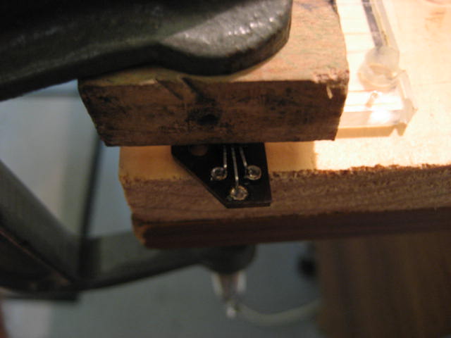
My plan was to tack each leg to the side of the hole, leaving the hole open to pass the leads into. It would then be easy to solder the three holes up after the board was in position and wired correctly. First, the legs of the IC had to be bent at right angles, the centre leg was 6mm from the IC and the other two were 3.5mm. That was easily done using long nose pliers and a vernier gauge. The IC was then positioned on the board, held tightly in a small clamp and tack soldered in position.
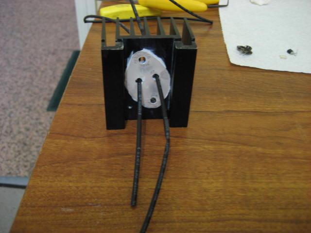
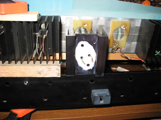
The next step was to fit the small board to the heatsink. That was fairly straight forward but the lead lengths were very short and it was hard to fiddle things into position. The important points were to get the heat sink the correct way round and ensure that the correct coloured leads went to the right hole.
After IC9 was fitted the heat sink was held face upwards and the leads for IC10 (MJ2501) were passed up into the correct holes, green on the left and orange on the right. I then put the mica insulator onto the heatsink and discovered problem two, the holes were in the correct place but their diameter was too small. The mica sheets were then carefully drilled to enlarge the holes. Conductive paste was applied to the mica and it was then positioned correctly on the heat sink.
Connecting IC10 was a hard job. First I tried to use those small coils to join the lead to the leg. Problem three, the diameter of the IC pins were slightly larger and there was no way that the coil was going to fit. My eventual solution was to get a solid solder joint between the two and position some heat shrink over the joint. This worked fairly nicely. After more paste was applied to the mica, the heat sink was finally twisted into position and screwed in place. Problem four, the profile of the IC was different to the original (the new ones are thinner) and the screws pass right through into the space where the amplifier board is. The screws had to be removed and some extra washers added to restrict the length of the screw passing through.
So, that was the first heat sink in place and fitting the second one was very much quicker. There were no problems this time round but I was lucky to spot that I had the wires the wrong way round before the soldering started. It just shows, no matter how careful you think you are, you still make mistakes.
The remaining tasks for replacing the two resistors and the trimpot were fairly routine.
After all of the components were refitted, I carried out a lot of checks, comparing resistance values at strategic points on all four amplifiers. The results were remarkably similar. I also checked that there were no low resistance paths connected to the 60v line. Since I wanted to keep the amplifier board and the heat sink assembly above the base so that I can carry out live measurements and adjustments, I had to do the following things.
Install temporary ground connections to the different panels that had been disconnected.
Ensure that any bare ended wires around the audio capacitors were not a risk.
Put a lot of cardboard insulation around the amplifier board, especially on the solder side.
My plan for the initial startup was to leave the tuner indicator out and PC14 not fitted.
At 21h00 on Tuesday, power was connected. The switch at the back was switched on and the new lights on the volume indicator all glowed for the first time. Then finally, I closed P5 and waited for 5 seconds before switching off. To my relief, nothing dramatic had happened so I switched it on again for a bit longer this time. No flashes, no smells so I switched it all off again. I will sleep well tonight and start again tomorrow. There are still many more measurements to take and adjustments to be done. No doubt there are also a lot of surprises in store.
Anyhow, so far, so good.   
Regards
Geoff
|
|
-
-
-
BenSA
 - Joined on 04-16-2007
- Durban, South Africa
- Posts 808
|
|
-
-
geearr
- Joined on 03-27-2008
- Gold Coast, Australia
- Posts 301
|
Hi everyone - thanks for the comments but it is far too early for congrats - those are reserved for when we hear some good sound out of this machine.
Even after the success of putting power on yesterday evening, I didn’t sleep well last night. I seemed to be dreaming about the shape of the new ICs and whether this was going to cause any problems. First thing this morning I was up and measuring them.
My concern with the shape of the TO-3 was with the thickness of the shoulder and the height of the cap itself. The insulated case which holds this IC is obviously designed for certain dimensions and the case has to put firm pressure on the shoulders so that the face makes good contact with the heatsink and the collector tab washer is also firmly pressed on the metal. If the height of the cap is too big then the pressure will be applied by the back plate and the tab washer will make a very poor contact. This worried me.
I measured the depth of the insulated case and it was around 8mm. If the cap height exceeds this, then the pressure will be applied incorrectly. From the IC specification sheet, it appears that the height of this particular cap is around 7.5mm so I didn’t have much to spare. Visually, the shoulder was up against the insulated case and as a double check, I measured the resistance of the cap to ground. On all the MJ2501s, the resistance was very low as the collector is grounded through the 0.12ohm resistor. On the MJ3001s, the resistance on all four amps were very high. I was therefore confident that I had installed the IC as well as possible. The lesson is very clear, check the physical dimensions of all replacement components thoroughly before you start. They are going to be different and this could have undesirable consequences.
After the relief of finding the ICs were probably going to be OK, I set about measuring the amplifier performance. I switched on the set and the amplifier supply voltage went straight to 61V  . The power draw was only around 21W so I was happy to leave it running. I then measured the DC voltage on the four cables to the audio capacitor. Bad news I am afraid, the left rear amplifier still measured around 60V . The power draw was only around 21W so I was happy to leave it running. I then measured the DC voltage on the four cables to the audio capacitor. Bad news I am afraid, the left rear amplifier still measured around 60V  whereas all the others were around 30V. All of my hard work had failed to fix the problem. However, I had to be positive as there were definitely four components in the circuit that were working now that hadn’t been working before. whereas all the others were around 30V. All of my hard work had failed to fix the problem. However, I had to be positive as there were definitely four components in the circuit that were working now that hadn’t been working before.
All of the voltages around the new trimmer were close to 60V and I reasoned that there might be a problem with TR2. In then set about measuring all of the voltages on TR1 and TR2. My results left me in no doubt that TR2 was also dead. The transistor that I had thought about replacing when I first started this project, but didn’t, turned out to be an error of judgment. I have now ordered new transistors and some replacement capacitors as well.
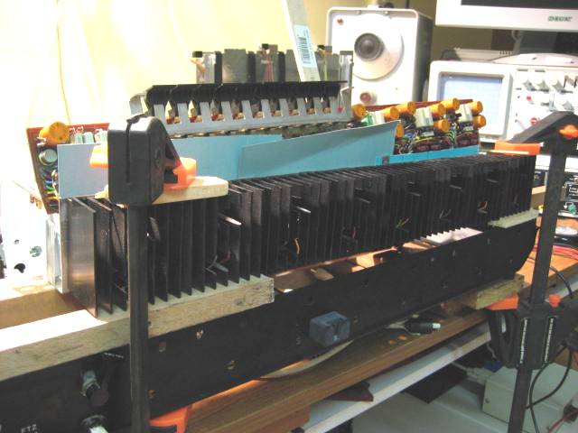
The one good thing that I have learned is that I can continue to run this beomaster with all of the boards hanging all over the place as long as I am careful. This makes it so much easier to replace many of the amplifier and preamp components and optimize the performance. It beats having to dismantle and reassemble things all of the time – a routine that invariably results in breakages. It also seems that this machine is going to hog all of my valuable bench space for a good while yet.
Back to waiting for the courier.
Regards
Geoff
|
|
-
-
Søren Mexico
 
- Joined on 09-13-2007
- Mexico city
- Posts 1,621
|
Amazing, golden works from the Gold Coast, congrats.
Beosound 3000, BL 4000, BL 8000, BG 2404,BG 5000, BG CD50, Beocord 5000, BM 901, BM 2400, BM 4000, BV S45, BV 3702. There is nothing we cannot do, but a lot of things we don't want to do!!
|
|
-
-
geearr
- Joined on 03-27-2008
- Gold Coast, Australia
- Posts 301
|
Thanks Soren, but all I am getting at the moment is a golden bill for spares. Anyway, at least it is all a lot of fun.
Geoff
|
|
-
-
geearr
- Joined on 03-27-2008
- Gold Coast, Australia
- Posts 301
|
Hi everyone
Unfortunately, my Beomaster quad project is clouded by bad news at the moment. I have been investigating the situation on the left rear amplifier and as mentioned earlier, transistor TR4 is sitting there with an open collector - emitter circuit. It was probably like that when I was given the machine and it was never identified as a firm candidate for repair. While this transistor remains open, this part of the circuit is not grounded correctly and will always stay at 60V. This provides incorrect base voltages to all three ICs. When power was applied after all my repair work, the emitter of IC8 automatically goes to 30V. However, when the base settled at 60V, it was only a matter of time before the high base / emitter voltage cooked IC8 once again (another one bites the dust!!). I have also learned that when IC8 fails, it does not go open circuit, but instead develops a short circuit from the collector to the emitter. That is the reason why the voltage to the audio output capacitor is currently sitting around 60V.
I have been studying this amplifier circuit in a lot more detail because I know very little about amplifier theories and electronics. No one has taught me and what I do know has been learned from experience. My logic tells me the following and there at least appears to be some good news:-
While TR4 is open, the base voltages on the ICs are all around 60V. Therefore, on IC10 (PNP) the emitter voltage can never be higher than the base and this IC remains off. Hence I suspect there has been no damage to IC10. The same logic applies to IC9, so on this occasion, I suspect that only one of the three ICs have been lost.
Since IC10 is still off, there is only a low current flow through the pair of ICs and all of the series resistors (0.12ohm) should still be OK.
Thinking back to the original problem with this amplifier, the faulty trimmer obviously had a big influence on the outcome. When the trimmer went open circuit, the base voltage on IC8 will have gone high. IC8 then goes short circuit and sets the emitter voltage on IC10 to 60V. At the same time, the disconnection in the trimmer resulted in the base voltage on IC10 going low and the high emitter/base voltage will have cooked IC10. With both ICs failed to short circuit, the full 60V was applied to the four 0.12ohm resistors and the weakest one will have acted as a fuse. That seems to be the reason why I lost the two ICs and one resistor. Also, the base of IC9 will have gone low and that will have blown as well. It all seems to make much more sense now. All of this mess from one sick trimmer??? I haven’t quite worked out how, but such a series of events may have even taken out TR4 on the same occasion. Quite a firework party, one night a long time ago.
So what did I do wrong? Well, with so many parts having failed in this amplifier, it was very difficult to diagnose its true condition. I think I did well to find the four failed parts but didn’t have enough information to identify that TR4 had gone as well. After replacing the four items and starting up, a faulty TR4 has blown IC8. I now hope that when I replace these two components, I will have an amplifier that works properly.
I have now ordered some more replacement parts including one extra set of ICs. This gives me two more attempts to get it right. If that doesn’t work, then my bank manager will shutdown this project and the Beomaster 6000 will be consigned to spares. If anyone can spot anything that I have overlooked or has any other good ideas, please shout now. By Wednesday next week, the fate of this quad will have probably been decided.
Regards
Geoff
|
|
-
-
geearr
- Joined on 03-27-2008
- Gold Coast, Australia
- Posts 301
|
Hi everyone
While waiting for spares, I have been able to check out the other three amplifiers and everything is looking good. First I checked the output voltages to the audio capacitors and they were nicely around 29V – no problems with the overall IC performance on those three.
The second thing I checked were the trimmers. I measured the total resistance of the track from the adjoining resistors to make sure there were no open circuits or high resistance points. Here I found that two of the tracks were standard 250 ohm but one was higher at 350 ohm. It does seem that this trimmer is an odd one but it works OK. Unfortunately there are no markings on any of the trimmers identifying their ratings - any comments ??
Next I measured the resistance from the variable connection to the two ends to identify how it was currently setup. All trimmers were then cleaned, lubricated and exercised several times. Finally, I measured the changing resistance while it was turned to ensure that there was a smooth operation. All of them looked very good and even the 350ohm trimmer was giving sensible readings. The resistance values were then reset to what they were earlier.
I then powered up the machine and went through the no load setting procedure. The factory standard was 7.2mV across the collector resistor to ground. The three amplifiers varied from 1 to 8mV and were all reset to standard. With the trimmers working well, one can set this value fairly accurately.
After the no load settings were finished, I measured the DC voltages at strategic points on each amplifier. This covered all ICs, transistors and the supply voltages. Now there is more good news that all of the amplifier DC voltages were very close to standard. So, it looks like there are three good ones and one more to go!!! At least this exercise has provided me with plenty of motivation to fix that left rear amplifier properly.
Regards
Geoff
|
|
-
-
geearr
- Joined on 03-27-2008
- Gold Coast, Australia
- Posts 301
|
Hi Everyone 
ICs arrived yesterday and Dillen's audio caps came today. Thanks Martin
Hard work putting it all together and there was a lot of testing to do. However, power was eventually put on and nothing sparked.
Finally, I heard the sounds of a radio station. What a relief and plenty of joy.
I will have a long beer tonight to celebrate and tomorrow I will write up my latest progress notes. Next, I will have a well deserved break before I start testing all of the functionality - that is going to take some time. Hopefully, it will not be too long before I start to put the cabinet and trim back together again.
Will keep you all posted on all the events.
Regards
Geoff
|
|
-
-
BenSA
- Joined on 04-16-2007
- Durban, South Africa
- Posts 808
|
|
-
-
Step1

- Joined on 07-06-2008
- Manchester
- Posts 961
|
|
-
-
geearr
- Joined on 03-27-2008
- Gold Coast, Australia
- Posts 301
|
Thanks for the comments
Progress remains good and all four channels are working well. Slow but sure remains the best policy.
The one problem that is holding me up and irritates me is the loud thud through the speakers when power is switched on. Any information on where best to find the solution to that one will be appreciated.
Regards
Geoff
|
|
-
-
tournedos
  - Joined on 12-08-2007
- Finland
- Posts 5,808
|
 geearr: geearr:The one problem that is holding me up and irritates me is the loud thud through the speakers when power is switched on. Any information on where best to find the solution to that one will be appreciated.
That seems to be a trademark of all AC coupled Beomasters. I never heard them when they were new, but I suppose there's no way to get completely rid of it - unless you want to retrofit a delayed speaker relay. My theory is that it gets louder if the supply voltages come up at uneven rates, so new caps might diminish it but I doubt that it would ever go away.
Great to see this Beomaster saved!
|
|
-
-
geearr
- Joined on 03-27-2008
- Gold Coast, Australia
- Posts 301
|
Thanks for the information Tournedos
I will assume that this machine was not sold with this characteristic. If I had bought it like that, it would have been returned next day. So there has to be a way to improve it.
There are a number of large caps on the power supply, a large 10000uF at the tail of the 60V supply, a 3000uF across the low voltage rectifier and a 1000uF around the switch. Are these the caps that might be causing the problem or are there others? Does the fact that the noise is evident at all amps point to the 60V supply capacitor? Are there any tests or measurements that can be taken to help identify the cause?
Regards
Geoff
|
|
-
-
geearr
- Joined on 03-27-2008
- Gold Coast, Australia
- Posts 301
|
Hi Everyone
I had a hard time getting this left rear amplifier to work so I will try to summarise my main learning points.
In phase 1 of the repair job, I replaced the three ICs, the trimmer and the resistor and thought that would do the trick.
After starting up, IC8 broke down and this fault was traced to TR4. If TR4 does not switch on, the trimmer branch goes to 60V and the high base emitter voltage kills IC8. After testing, it appeared that IC9 and 10 had been spared and I decided to replace TR4 and IC8. Also, for good measure, I replaced TR3 as well and the three main electrolytics..
After the next start, there were more problems and it now became clear that IC9 was faulty. As I was fast running out of spare ICs, I now decided to replace them all irrespective of their apparent condition. This time the amplifier started up properly and all of the DC voltages were now very similar to the other amplifiers. To complete the picture, I replaced the three main electrolytics on each of the other three amplifiers as well.
These mistakes have taught me that with this particular amplifier, you might as well replace the three ICs, two transistors and three capacitors in one hit. It is the more expensive option but it eliminates the risk of having a hidden fault that is simply going to destroy the new parts. If all of these items had been removed in one go, it would have also been much easier to identify any faults with the remaining components. Oh the wisdom of hindsight!!
The cost of the parts that were actually needed to fix this amplifier was only about A$30 but I also wasted another $35 inadvertently damaging ICs. I suppose this is the price we pay to learn but really, it is all part of the fun of making these old units work again.
Regards
Geoff
|
|
-
-
-
-
geearr
- Joined on 03-27-2008
- Gold Coast, Australia
- Posts 301
|
Thanks BenSA
I was just wondering what the situation was with other 6000 quad owners and you have answered my question. Obviously, you have got used to your "small thud" and now you don't hear it. Unfortunately, my machine is still opened up with parts hanging off it and when I hear that noise, it scares me to blazes. I keep looking for a screwdriver that I have left on the PC board!!
Hopefully someone will be able to suggest what parts can be replaced to improve the situation and then maybe, mine will be as quiet as yours.
Regards
Geoff
|
|
-
-
geearr
- Joined on 03-27-2008
- Gold Coast, Australia
- Posts 301
|
Thanks for the ideas Olly
At the moment, I will try the replacement options and see how far that gets me. I am not really into "new developments" and have enough trouble with existing technology. So when that time comes, I will ask you to send me an updated circuit diagram and we can take it from there.
Regards
Geoff
|
|
-
-
-
-
geearr
- Joined on 03-27-2008
- Gold Coast, Australia
- Posts 301
|
Thanks Eugene
Pleased to hear that you are watching - I can always do with some help from someone with your experience. Have you worked on the "quad" before? If you answer "yes", be careful because you will be inundated with a stack of questions.
Regards
Geoff
|
|
-
-
geearr
- Joined on 03-27-2008
- Gold Coast, Australia
- Posts 301
|
Hi Everyone
When you change the ICs on the BM6000 amplifier three or four times you quickly find an easier way to do things. My first attempt took two of us nearly two hours whereas later changes took less than half an hour. I thought that I would document my procedure for changing the ICs and if anyone has an improved version, please feel free to amend it.
Arrange the two coloured wires so they are straight and correctly oriented. For IC8, grey is on the left and red on the right. For IC10, green is on the left and orange on the right.
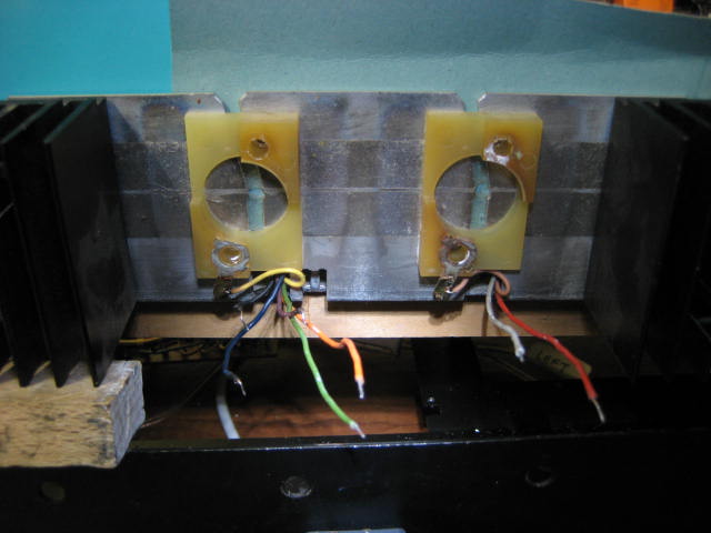
Use conductive paste to stick the mica insulator to the heat sink.
Cut two pieces of heat shrink tubing about 150 mm long and passed them through the two holes in the heat sink which take the cables and IC leads.
Position the heat sink in its correct orientation near the insulated IC holder and then, rotate 180 degrees towards you. This leaves the fins facing the other heat sinks and the heat sink is now upside down.
Slip the two tubes over the wires and slide the heat sink right up to the unit. The tubing can then be removed leaving the two wires sticking out of the holes.
Park the heat sink on the back edge of the base.
Check the IC orientation is correct and matches the holes in the heat sink. Base is on the left and the emitter on the right. Solder the two leads to the IC.
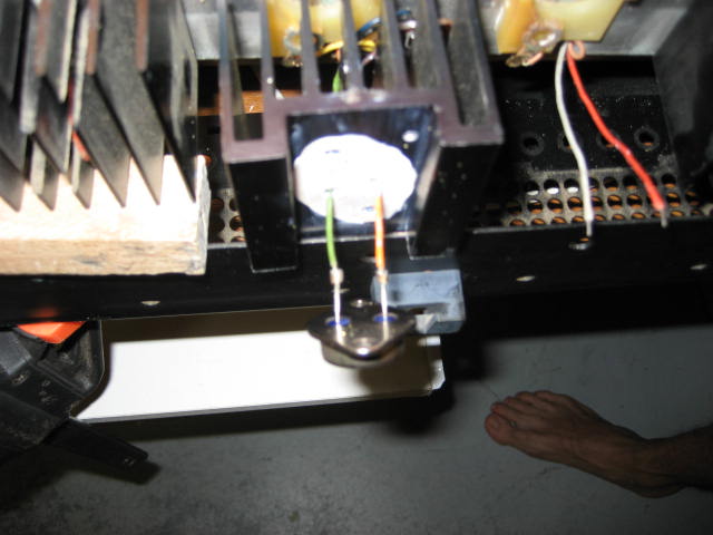
Put conductive paste on the exposed face of the mica insulator. Bring the IC close to the heat sink and press and slide to get a good joint. The solder joint is now in between the fins of the heat sink.
Rotate the heatsink 180 degrees towards the unit, ensuring that the two leads lie nicely between the fins. Push the heat sink and IC to fit it into the insulating block.
Fit the two screws with the insulating sheath and washers. Tighten gently to ensure a neat fit. After everything is checked, tighten the screws firmly, hand tight.
Check that the solder joint has a good clearance from the fins.
That summarises the procedure that I used and it is highly likely that we will need it again sometime
Regards
Geoff
|
|
-
-
geearr
- Joined on 03-27-2008
- Gold Coast, Australia
- Posts 301
|
Hi Everyone
This project is now starting to near its end – that is for the time being at least. After it became clear that the faulty left rear amplifier was now working properly, I started to put the machine back together again. This turned out to be a fairly long task because I was regularly testing for shorts, a big risk on this unit where a lot of boards are crammed very tightly together with precious little free space. For those that are interested, the sequence for re-assembly was basically as follows:
First I unclamped the heat sinks and lowered them back into the base. Then I replaced the four screws holding the amplifier casing and partly lowered the amplifier board PC11 back into the casing.
Refit the clamp holding the RF front end box to the base. Four screws were used and I carefully rechecked the ground connections.
Refit the socket assembly to the base using six screws.
Cut sections of insulating board and placed them between the amp casing and the solder connections of PC11. Rechecked the resistance and made sure that there were no shorts to ground. Switched on the unit and everything checked OK.
Switched off, fitted and reconnected four audio caps. Switched on and rechecked the voltages around each amp. Everything seemed to be good.
Switched off and connected the aerial and two speakers. Finally pushed the amplifier board completely into its slot, carefully lined it up and checked all of the insulating packing. Took some time to tidy up the wiring looms and make them fit neatly. Pressed the front speaker button. Checked the 60V to ground resistance and was still OK. Turned volume to minimum, switched on the unit and activated P5. Slowly increased the volume and then adjusted the tuner. Got three red lights and a strong stereo channel. Finally, sound from the speakers at long last.
With the speakers connected, there was the loud thud when you switch on– quite scary! When I tried again, the audio on the front right channel was crackling and sounding like a poor connection. Since the signal path was OK on the two rear speakers that could not be the problem. The most likely problem areas were crackly potentiometers or the tone board. When I moved all of the variable pots there were no crackling noises. Used a wooden brush handle to tap the right front part of the tone board and the signal started playing up.
Took off the tone board, four plastic clips. Replaced the four large 100uF electrolytics while they were accessible. With the radio working, tapped the various components and wires. Problem was the 10uF tantalum C41. Replaced and the crackling noise disappeared. The signal path is now very strong and gives an excellent sound.
Started checking various functionalities whilst putting the unit back together. Tested the Hi and Lo filters and they work correctly. Tested the pre-set tuning pots and P5 could well be stuck. Removed the tuner board and found that it looked like a sealed unit. Could only spray clean and lubricate. When tested later on, the P5 frequency was still fixed at the same value. Since the wheel and cog goes around properly, the axle connection to the pot may have broken or the pot might be damaged. Need to find out whether these assemblies can be dismantled or not.
A black heat patch indicated the presence of a hot spot on PC2. This was underneath resistor 2R44 going to emitter of TR8. Replaced the resistor and set it well above the board to allow some cooling.
Replaced the indicator tape on the volume pot. Had to use two small wedges (oversize toothpicks) to stop the tape falling out. The “V” shaped wedge was then not too difficult to fit.
Tested all of the motor and clutch movements and they worked OK. Lubricated the motor drive gears. The general clutch movement sounded a bit clunky but it might be quieter when the covers are all in place.
Replaced PC14, the “remote receiver” board using two screws. Positioned some new insulating board in front of the solder connections.
Replaced the potentiometer assembly but it was very difficult to locate these small screws. Finally put a long screw from underneath to locate one end and then was able to fit the small screw at the other end. Easy after that.
During testing I noticed that one lamp out of the six display lights was very dim. Took it out but it tested OK. Since the lamps are connected in series, the other working light had to be restricting the current. Took out the second bulb and the resistance was 43ohm compared with 17 ohm on the new ones. One of the bulbs that I replaced must have a different rating. All lights are now working properly.
Replaced the tuning indicator – two screws for the hinge, three screws for the holder and two solder joints. Had to readjust a few of the looms to get it to sit properly. The string was easy to replace and the cardboard holder kept it all in place. Switched on to confirm all of the lights worked properly.
Replaced the rear panel over the heat sinks – four screws at the back and two on top. Noted how it pushes the amplifier board forwards. No problems with the insulation detected.
Put on the black display panel and noted that the potentiometer display was sitting too high. Removed the two holding screws and adjusted the four static screws. Turned rear screws clockwise in and front screws anticlockwise out, only about one turn. Also removed a bit of insulation board that was fouling. Put the two fixed screws back and the display panel now sits lower.
Put the front panel into position. Had to adjust the relative positions of the wiring looms to allow the panel to come down to its normal position. Important to keep the wires away from the potentiometer wheels. With the black display panel out, noted that the aluminium edge of the front panel was going to touch the tabs on the lamps. Had to bend the tabs to make sure that they were well behind the black plastic holders.
Assembled the black panel and the front panel. Lubricated the tuning wheel bearings and replaced the wheel in the opening. Tightened up the holding nut just finger tight for the moment.
Fitted the woodwork frame but it was not the best fit because the sides were slightly bowed. Switched the unit on. Barring the thud, sounds OK with the four channels working properly. At the moment, I power up with the speakers off and only switch them on when the unit has been on for a short while. The display panel is 100% OK. Connected a tape deck and played some decent music on Aux2. Almost there…..
So here it is powered up and singing
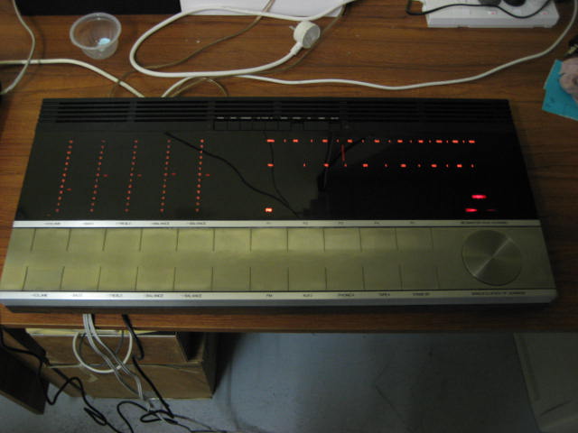
Only one more thing to do and that is prepare the list of outstanding faults that will need fixing some time in the future. So close, yet so far but so satisfying.
Regards
Geoff
|
|
-
|
|
|