|
Untitled Page
ARCHIVED FORUM -- April 2007 to March 2012
READ ONLY FORUM
This is the first Archived Forum which was active between 17th April 2007 and
1st March February 2012
Latest post 11-19-2011 9:38 AM by Step1. 81 replies.
-
 05-08-2011 2:18 AM
|
|
-
 geearr
  - Joined on 03-27-2008
- Gold Coast, Australia
- Posts 301

|
Hi Everyone
Late last week I was very lucky to be given an old Beosystem 6000 quad. This system didn’t work and had been stored in the garage for quite a long time. The whole package weighed a tonne so the owner was pleased to see it go and reclaim some of his valuable real estate. However with some TLC, the various parts are already starting to come alive once again. So far, the Beogram 4002 quad is looking very good and producing a nice stereo sound. Two P50 speakers have also been salvaged from the set of four and they sound great. The last two unfortunately were in poor condition and they will probably remain in the “for spares “ category unless I can be bothered with a complete fabric replacement job.
That leaves the Beomaster 6000 to fix and that is where my problems are at the moment. This is the first time that I have seen inside one of these machines and my first impression is that it must rank as one of the least friendly of B&O units regarding maintenance access. I have fixed some switching issues and some lights. I have replaced the perished rubber connection at the volume motor and lately have checked that the signal path is OK right through to the amplifier. The switching functions and the radio tuning seem to be OK so what remains? Well, I haven’t heard a single sound out of the speakers so far – not even a hum, a scratch or a whistle. Headphone ports are quiet as well. All four amps sound totally dead.
Normally, problems in the amplifiers don’t worry me, after all, one checks the signal going in and then traces it through the amp until the problem is identified. The hassle with this unit is the lack of decent access to the board (PC10). The output switches are also mounted on the same board so these cannot be checked either.
So my question to the “quad” experts is - how do you gain safe and suitable access to the amplifier board, the 60v power supply and the switches. I would like to have power on with this board in a service position so that I can trace the signal path. Any tips or tricks for working with this machine would also be very welcome.
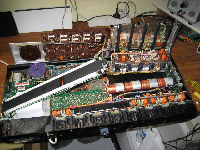
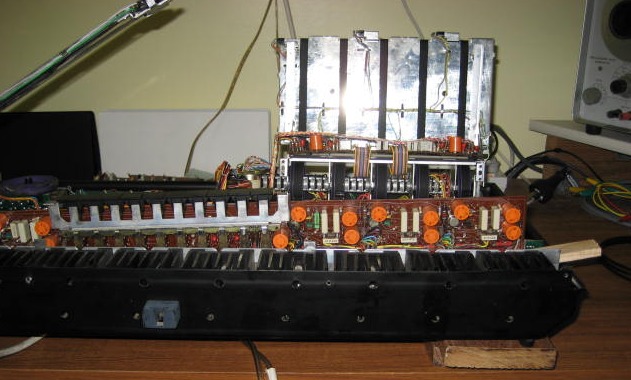
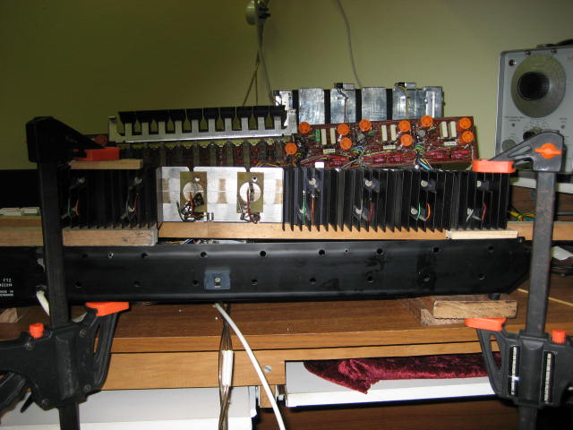
I have enclosed a few photos showing the congestion inside this box. All ideas and comments are welcome because my problem may well be something else and not the amplifier.
Thanks for your help
Regards
Geoff
|
|
-
-
-
geearr
- Joined on 03-27-2008
- Gold Coast, Australia
- Posts 301
|
Thanks Peter
I have downloaded everything that is available and it does help a great deal. The comments on BeoCentral are very valid and makes one wonder whether this is going to be worth the effort. The amplifier board in my unit is certainly warped and copious amounts of polystyrene foam have been used to help with the isolation.
I have already found that the tabs on the output capacitors are badly corroded and very little AC is passing through them. One of the amplifier channels may also be faulty too. It all points to an expensive re-construction and given the shortage of rave reviews on the performance of this machine - I wonder?? 
Regards
Geoff
|
|
-
-
Step1
 
 - Joined on 07-06-2008
- Manchester
- Posts 961
|
Geoff you must try to repair this stunning hifi! There are a few people whom have previously written that they like the warm sound of these hifis and they are very desirable to collectors...
I would do this as a slow-burn project if you are not overly keen.
Personally I cannot wait to get my hands on one of these! I don't think I would keep it, mostly due to lack of room...
|
|
-
-
-
geearr
- Joined on 03-27-2008
- Gold Coast, Australia
- Posts 301
|
Thanks for the positive comments and I will probably keep going until I get it right – just because I like a good challenge. I would also like to see if these machines are as visually impressive as they seemed in the old pictures.
I have now found that all of the large 5000uF audio cans have failed. In two of them, the terminals just fell out (bad corrosion) when I loosened up that long train. Now I have to find four replacements for those. I put an old 4700uF can in one of the channels just for testing purposes. The good news was that that channel finally sprung to life and at long last I have finally heard some sound from this unit. Not the greatest but at least there was something. Still, I now have a comfortable feeling that many of the boards might be working after all.
If anyone has any thoughts on a suitable replacement capacitor, I would like to hear them.
Regards
Geoff
|
|
-
-
-
lausvi
  - Joined on 04-16-2007
- Helsinki - Finland
- Posts 498
|
 tournedos: tournedos:
Something like this? I have no idea where I got these, I've had a couple rolling on my desk for ages. Size 40 x 29 mm. If the size is suitable, at least you know that these exist somewhere.
I have one, too. It's from Partco, and in the webshop it says it's a Panasonic.
Bang & Olufsen - The art of controlling sound, picture and light
|
|
-
-
hemenex

- Joined on 04-23-2007
- Posts 375

|
look at the squared uppercase "M"
It IS a Panasonic 
Although newer ones in 40x30mm seem to be 80Volt Types
Gunther
|
|
-
-
geearr
- Joined on 03-27-2008
- Gold Coast, Australia
- Posts 301
|
Hi everyone
I have been doing some more work and research on this project and the current status is as follows:
Thanks for your input regarding potential capacitors. In the meantime, I have been in touch with Dillen and he has offered to provide me with four capacitors that will be suitable for this task. I look forward to finding out what he is going to send and one day, I will hopefully see how well they perform.
The output capacitors have been disconnected and I have done some more work on the signal paths under no load conditions. It is now clear that the left rear amplifier has a major problem but the good news is that the other three are performing almost identically. That gives me some solid references which I can use to assess the situation in the faulty amp.
I finally found a piece of suitable rubber tubing for making the connection between the volume control motor and the shaft with the clutch assembly. Tests have shown that everything works well in this area and the variable volume is being passed nicely into the three working amplifiers.
So now, my new main problem is how to fix this amplifier?? I will start by trying to source three replacement ICs and the two transistors because I might as well replace the lot after putting in all of the effort to dismantle it. But --- the most serious difficulty (which prompted me to start this thread in the first place) is what is the best way to dismantle this machine for ease of access. I can currently only raise the amplifier board about 10mm before it gets very tight and that isn’t going to be enough to work on it neatly.
The good news is that I have now reduced the dismantling scope to some extent which obviously helps. The front part of the machine is relatively easy to access and I have taken out PC14 to give more room around the volume module and the output capacitors. However, I am finding it very difficult to access anything around the transformer, PC6 & 7 and the amplifier section
Has anybody carried out any repair work on the amplifier board PC11 and replaced the main ICs??? I would love to hear from you.
Regards
Geoff
|
|
-
-
geearr
- Joined on 03-27-2008
- Gold Coast, Australia
- Posts 301
|
Hi everyone
Obviously there are no experienced quad dismantlers out there who want to be identified so I have decided to dismantle it all myself. If it all goes pear shaped – well, the unit wasn’t even working in the first place and I will have another bucket load of spares for my other projects.
Some tests on the faulty amplifier have confirmed that one of the ICs has shorted and one of the 0,12ohm resistors has burnt out. I am sure there is more in store as well. So with some major replacements to do – here goes…………
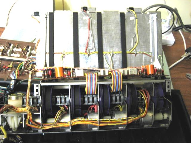
First, I wanted to clean out the area and loosen as many of the things that were holding the fixed wiring in place. I had taken out PC14 on the side and disconnected the four audio capacitors. I then removed the four screws holding the bracket on the front end box and that helped unfix the main wiring loom. Next I took out the six screws holding the socket panel to the base and that gave a bit more movement. The situation then looked as shown below.
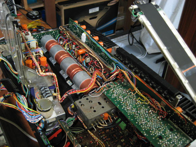
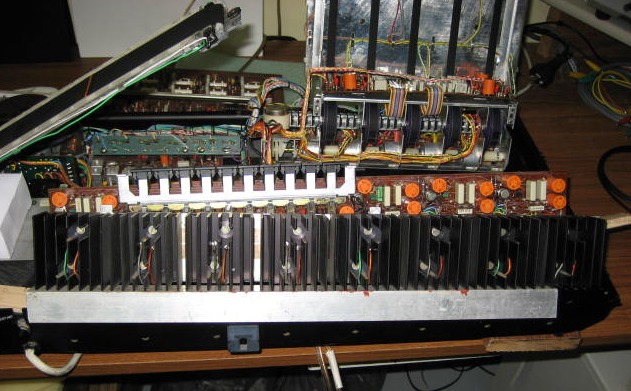
With a bit more stretch in the wiring, the amplifier board could be lifted slightly but there is still a large portion which is inaccessible – see below.
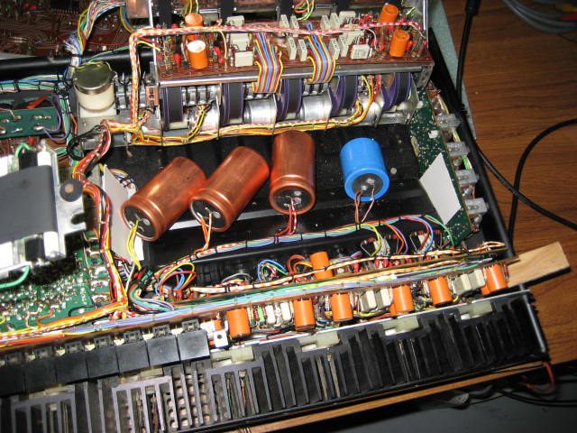
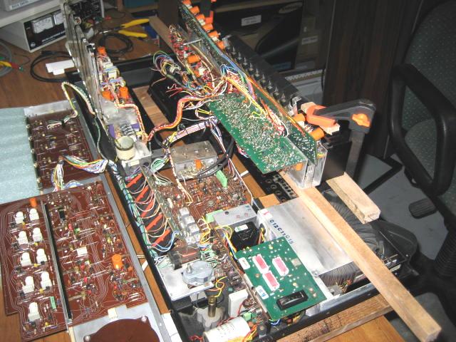
I then removed the four screws from the underneath that hold the amplifier assembly in place. The heat sink can then be lifted and I parked it on top of a piece of aluminium angle. Now I hope I can take the heat sinks off and remove the main ICs.
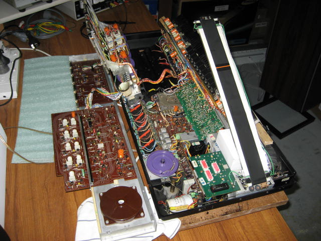
So there we have it for the moment. The whole thing looks a bit of a mess as shown below. It certainly makes one appreciated the modular development that came soon after. By comparison, the Beomaster 8000 comes apart very neatly although I didn’t think so at the time.
This project is now going to sit for a while, awaiting spares. No doubt I will hear many comments from the suppliers like “they don’t make those any more – mate” but eventually something will turn up. The next step will be to dismantle the heat sinks.
Regards
Geoff
|
|
-
-
geearr
- Joined on 03-27-2008
- Gold Coast, Australia
- Posts 301
|
Hi to everyone interested in “Quad” repairs
I have now removed the two heat sinks holding the ICs for the Left Rear amplifier. This was fairly straightforward after lifting them clear of the main baseplate. I started with the right one holding the MJ3001 IC because it is simpler, took out the two screws and moved the heat sink away from its supporting frame. There is sufficient cable length so that the heat sink can be moved past the solder joints and this allows you to get a decent access to the joint. On this occasion, I decided to snip the wire as close as possible to the joint and effectively lost about 5mm of cable length. Once the wires have been cut, the IC and the mica isolation can be easily removed.
The second heat sink with the MJ2501 IC is a bit more fiddly. After moving the heat sink towards the joint, it was first necessary to unscrew the smaller IC MPSA13. Take care not to lose the small brass support bush. After this small board was taken off, the wires could be cut and the setup dismantled as before.
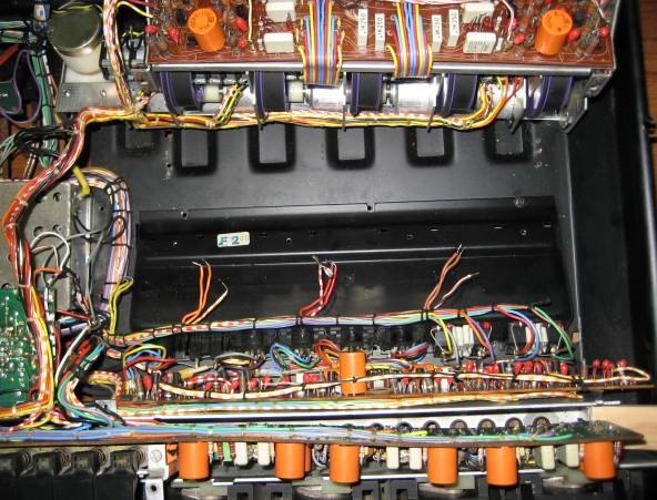
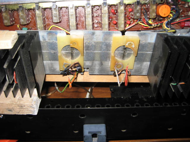
Empty space after removing the two heat sinks:
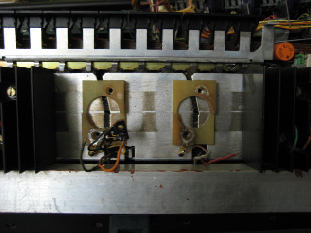
The whole area needs to be thoroughly cleaned and the collector tabs were found to be a bit rough. These were lightly buffed with a fine emery paper to ensure a good electrical contact.
Parts removed:
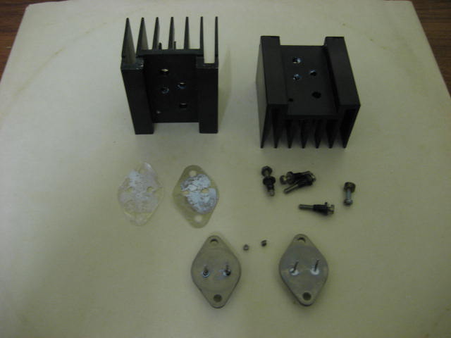
The two ICs were checked and both found to be faulty. I removed the four small coils which are placed over the solder joints and cleaned them out. I can use them again provided that I can get good enough access to the joint. Does anyone know why the cable is joined to the IC in this way? I noticed that one of the other ICs has been replaced in the past and this one just has a direct solder joint on the IC leads. Those little coils have been thrown away!
I now await the delivery of spare ICs and in the meantime will have a good think about how I am going to get these items back together again neatly.
Regards
Geoff
|
|
-
-
-
geearr
- Joined on 03-27-2008
- Gold Coast, Australia
- Posts 301
|
Hi Everyone
Thanks for the encouragement Peter, I am going to need plenty of that because there is still a long way to go.
During my free time waiting for parts, I thought that I would take a look at the rack of potentiometers that are just sitting there. My first impression was that the large plastic pulleys with the drive belts were lying crooked. When I put a straight edge across the front, the various wheels were out of alignment by up to 6mm. I just had to straighten them out.
The service manual gives a pretty good idea of the general arrangement and it clearly shows that there is a “tongue” on the potentiometer housing that must sit properly in a corresponding groove. I guessed that these pots had been fiddled with a long time ago and had not been properly installed.
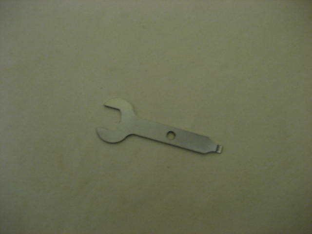
One of the hassles with fixing these is the very thin spanner that is needed, a 10mm nut opening and a thickness of no more than 1.5mm. I was just about to start to fabricate my own spanner when I remembered that my Dremel uses a very thin spanner and it turned out to be perfect for this job. If you have a Dremel then this job is going to be very easy.
After loosening the nuts, a small twist on the potentiometer housing lined up the tongue and groove and the units pushed in easily. After checking all five pots, I now have five perfectly aligned pulleys and everything looks so much better now but I am not sure whether all this work is going to translate into better performance. Still there is always satisfaction with perfection and in many ways, that is what B&O is all about.
Regards
Geoff
|
|
-
-
geearr
- Joined on 03-27-2008
- Gold Coast, Australia
- Posts 301
|
Hi everyone
I thought that I would do some more work on the potentiometer assembly because non of the lights were working. The lamps installed were 12v, 1W wedge based and after they had been taken out, five of the six were found to have failed. On this unit, the lamps are wired as three parallel circuits of two lamps in series. Hence if one lamp fails, two lamps will not light up. The series circuits are not arranged as “opposites” but are paired with the next opposite one along. I suppose that results in a less dramatic reduction in the light distribution when two lamps drop out.
First, the lamp socket had to be taken off the metal bracket and that was a delicate job given that the fragile black indicator tape was very close at hand and the wiring was not very flexible. Anyhow, it was possible to squeeze all of the lamp holders out but one of the wires broke off in the process.
The lamps were extremely hard to remove from the socket and they had to be levered out using some thin, long nosed pliers. Eventually they were all out and then it became clear that most had failed. This was surprising as I had expected to find three failed and three good lamps.
The lamps were all replaced and tested before reassembly. This was a worthwhile exercise because two of the new lamps didn’t light up when I put 12v across the holder terminals. The reason was the poor design of the contacts and they had difficulty making good contact with the wire leads on the lamp. I removed all of the lamps and bent their contact wires outwards so that there was a better chance of the wire matching with the holder. This done, all lights illuminated as expected when they were tested individually and in pairs.
When it came to refitting the lamp holders, five of the six went on fairly easily. However there is always one dog in a group and this one was the lamp that sits just above the volume potentiometer. The cable length was very short, the cables were very inflexible and there wasn’t much space available. I was really concerned that I was going to damage the indicator tape.
The only solution was to take out the tape and that was done fairly easily. The large plastic wheel holds the ends of the tape using a “V” shaped wedge. I was able to slide the wedge out by pushing it with a small screwdriver. It came out very easily and the tape slipped off. Putting it back on again is not going to be such a simple task so that can wait for another day.
With the tape off, it was easy to put the last lamp holder back in place. All lamps were tested in situ and worked well. Another job done.
Regards
Geoff
|
|
-
-
geearr
- Joined on 03-27-2008
- Gold Coast, Australia
- Posts 301
|
Hi everyone
After all of the recent work on the potentiometer assembly, it became clear that this unit was difficult to park in a stable position. To work on the amplifier side of the beomaster, the assembly has to be put in a vertical position or slightly inclined to rest on the front of the base. If you leave it upright, you always tend to knock it and it goes crashing over. There is a serious risk of damaging indicator tapes or other components.
My solution was to make a small bracket from a piece of Perspex, about 20mm wide by 50mm long. I drilled a 3.5mm hole at a point which was roughly above the mounting hole in the base plate. I then used a long M3 screw, nut and washers to clamp the Perspex in a position where it holds the volume assembly in place. Now I can work safely on the other parts around the amplifier without have to worry about this particular part.
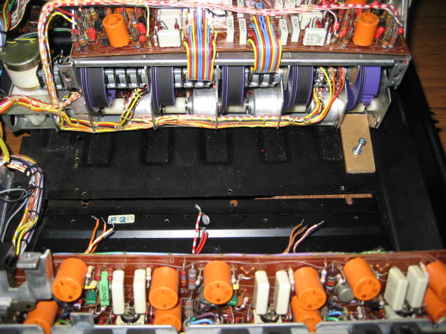
Later on, I made another clamp for the left hand side and fixed it in the same way. Now the potentiometer assembly definitely will not move.
Regards
Geoff
|
|
-
-
Dillen
  - Joined on 02-14-2007
- Copenhagen / Denmark
- Posts 5,008
|
Nice work !
Typical to see that it wasn't put together correctly by a previous "repairer".
It's not the easiest Beomaster to work on.
I think, the original service manual came with a tool for the potentiometers, mine did,
but the Dremel solution is great.
The little wedges are not as difficult to work with as you may think.
They slide out to the side when dismounting them, as you've found out and they
simply squeeze and clip back in (rather than slide).
The thin band will show bends where it was attached for years, hold the band in position
with the two ends down the hole at their old bends and simply insert the clip.
If you don't squeeze the clip more than needed, it won't break and if you do it this way, the
band will not be damaged. It's thin but not very fragile.
To the right of that large potentiometer group, there is a ground connection point where
a bunch of black grounding leads meet up.
It's not uncommon to see one or more breaking off, especially while servicing, so it's generally
a good idea to check them all, pull them slightly to have them reveal any soft spots.
Caps etc. on it's way.
Martin
|
|
-
-
geearr
- Joined on 03-27-2008
- Gold Coast, Australia
- Posts 301
|
Thanks Martin
These are the invaluable tips and tricks that I really need. Keep them flowing because it increases my chance of success substantially. I hate squeezing plastic things because Murphy's law has never been on my side!!!!
Regards
Geoff
|
|
-
-
geearr
- Joined on 03-27-2008
- Gold Coast, Australia
- Posts 301
|
Hi everyone.
The next challenge was to remove the tuning indicator because this was always getting in the way of things. I had it parked at an angle resting on a small box but it was always a nuisance when working on the amplifier parts. My additional motivation was that I wanted to lubricate and check the various components that move because the tuning operation felt a bit rough.
One of the jobs that I have learned to hate is the threading of these tuning systems. Plastic parts tend to break, strings tend to snap, springs won’t go on easily and a 30 minute job always ends up taking a morning or a day. This time, I thought that I would try something different.
First, I wound the tuning disc fully anticlockwise and then started photographing the string route, the looping around the different components and the wiring. Next I unsoldered the two leads that power the four indicator lights. I also marked the position of the orange indicator at its full travel location using a light pencil mark on the plastic casing, just in case it moves.
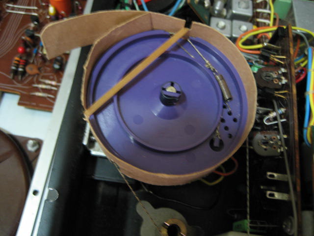
Taking the string off is fairly easy because there is always sufficient slack to ease it off one of the intermediate pulleys. Thereafter, the loops all fall off and create a general mess that has to be sorted out in the re assembly process. I decided that I wanted to keep the string in position around the main tuning wheel and I would hold it in place by wrapping cardboard around it. The diameter of the wheel is about 66mm and a piece of cardboard about 250mm long and 20mm wide should do the trick. There was also a small pulley at the top end of the track that I wanted to keep the string attached to, so I wrapped an elastic band around it a few times.
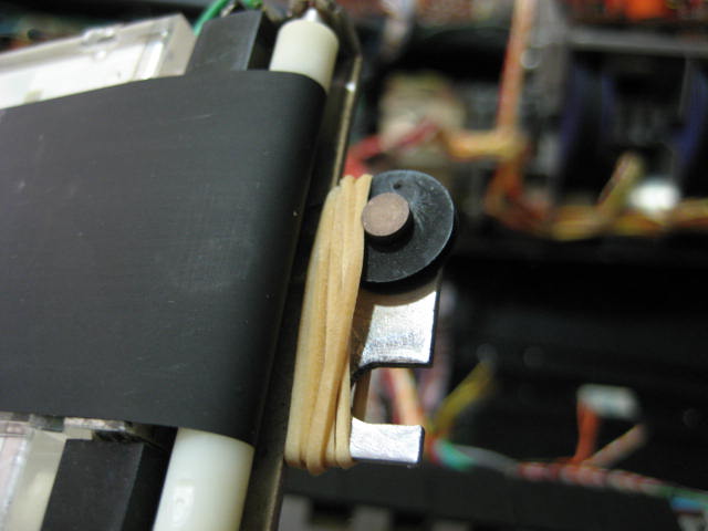
By holding the card in place, I marked the positions where the strings emerged. I then cut two slots at these positions which went to the middle of the width of the strip. When the card was wrapped around the wheel, two other slots would hold an elastic band which would keep the cardboard in place. Finally where the ends of the cardboard overlapped, I joined them using two staples and a very small stapling machine. The following picture shows the cardboard being fitted before the wheel was removed.
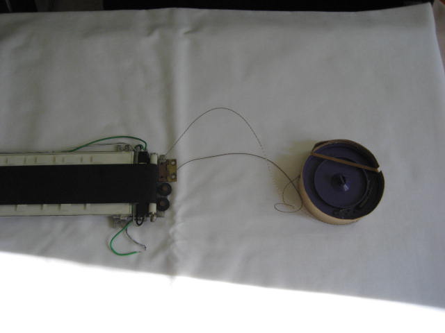
When my makeshift strap was in place, I slipped the string off from one of the pulleys. I unscrewed the two screws holding the hinge of the indicator frame and took the indicator off. Finally, I released the spring clip that holds the wheel on the shaft and took that off. The entire assembly now sits ready to put back and time will tell if this is going to be an easy or a difficult task.
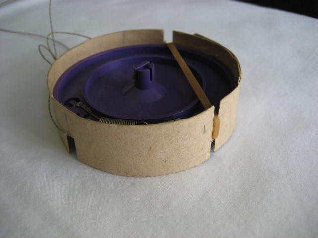
When the wheel has been taken off it is easier to see how the cardboard has been fitted around it.
The good news is that I now have a less cluttered space to fix up the amplifiers. I can now think about how to prop up the heat sink assembly to make the IC replacement easy.
Regards
Geoff
|
|
-
-
Step1
- Joined on 07-06-2008
- Manchester
- Posts 961
|
Super thread Geoff you must be tackling the most awkward bit of kit B&O ever made as far as I am aware! Keep up the good work!
BTW I prefer to sketch all details of the drive cords then remove from the main wheel tensioner springs - I like your cardboard solution with the dual use of the slots good thinking!
|
|
-
-
-
geearr
- Joined on 03-27-2008
- Gold Coast, Australia
- Posts 301
|
Hi everyone
Thanks for the recent feedback. I was interested to see the latest application for blue tak but judging from the amount used, I would have to order a bulk consignment.
Back to the project - now that the tuner indicator has been removed and the potentiometer assembly clamped properly, I had another go at making the amplifier board more accessible. I had a good look at the routings of the cable clusters and from the back, they seem to come in from left to right. So if the amplifier board is to lift up, it needs to move to the left where there will be more slack.
I was able to lift the amplifier and switch frame well above the base plate and put a long wooden section through to support it. As it tends to tip towards the front of the unit, I then clamped the heat sinks to the back of the base plate. This had to be done leaving an open area to work on ICs so that I can twist them into their final position. The final resting place for the assembly is shown below
This is now the latest view from above – quite a mess of heavily stretched wires. This whole machine is starting to look like a real dogs breakfast. At times, it feels as challenging as removing my old Landrover engine!!!
This is a view of the access that I have reinstall the ICs, I still have to remove that remaining IC. In the meantime, I have carried out a dummy run using the components that I have taken out and I think that I have got a reasonable technique for putting everything back together. I would definitely like to have much longer cable lengths to work with but that is wishful thinking. In any event, I have worked out that I am going to require an assistant to help with the positioning, holding and soldering exercise. Guess who!!
The amplifier board has been heavily stretched from the frame and as you can see is now parked across a nail. This gives reasonable access for replacing the faulty resistors and trimmer.
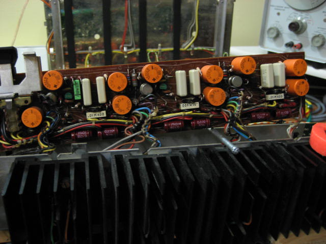
Finally a closer look at the two R12 resistors that will have to come out. The trimmer is parked below the two white capacitors. Not much room to work in here.
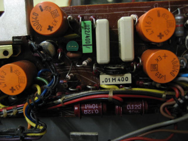
My final thought is whether to replace those orange capacitors?? They probably do need to be changed but I don’t really want to swap to much at once. Perhaps I should first change the ICs and resistors, set up the unit for a live run and get that right first. If and when everything shows that the four amplifiers are useable once again, maybe I should make another project for replacing capacitors. Any thoughts on that issue?
Regards
Geoff
|
|
-
-
-
tournedos
 - Joined on 12-08-2007
- Finland
- Posts 5,808
|
I also try to avoid changing too much at a time if the patient is not working when I begin. In my experience those orange Roedersteins aren't as often bad as the dark red brownish ones which can actually show cracks. Also, marginal caps aren't that critical in a full analogue construction. It'll usually work nevertheless and you can worry about audio quality later.
But do yourself a favour and get an ESR meter - I have one of these and I love it so much, I can't begin to count the hours it has saved:
http://clientes.netvisao.pt/greenpal/evb1.htm
You can almost always measure the ESR with the cap still in circuit as the test voltage is too small to bias semiconductors, so it makes a speedy job of tracing for possible bad apples. Doubles as a tweeter tester as well, there's a nice quiet chirp when the meter is doing its job
|
|
-
-
geearr
- Joined on 03-27-2008
- Gold Coast, Australia
- Posts 301
|
Hi everyone
I have now removed some more parts from the Left Rear amplifier circuit and the situation is as follows:
0IC8 and 0IC10 are out and both had failed.
0IC9 is now out and has also failed.
11R48, the 0.12ohm resistor is open circuit
The matching emitter resistor 11R49 is out but was OK
11R41 trimpot is out. This was definitely open circuit on the 60v side.
I must admit that I am surprised to see just how many components have failed – far more than I am normally used to finding. To the list above, I should also add the four large audio capacitors 0C8, 9, 14 and 15. Perhaps even more surprising is that the machine continued to operate without blowing up altogether!!! Unfortunately, the cost of refurbishing is continuing to escalate rapidly.
I have tried to test a number of the remaining parts where the connections have been cut but there is still too much interconnection to contend with. With four amplifiers sharing a common 60v supply and ground connection, getting any sensible readings is just about impossible. However, the results seem to indicate that the other two low value resistors 11R45 and 46 are probably OK. Some other resistor networks are also OK.
At the moment, my hypothesis is that the trimpot failed and this upset all of the base voltages on the ICs. The heavy currents that resulted damaged the ICs and resistor. Many of the front end resistors check out OK so I am hoping that 11TR3 and 4 are still good. By the way, it is normal for my hypotheses to be way off the mark.
Thanks for the comments on the capacitor replacement options. Tournedos, - that gadget for testing caps in situ looks quite attractive at that sort of price. Will definitely think about that option. Also, your comments that those orange caps do not have a history of unreliability is a relief . This makes me think that it is best to leave them in place for the moments and then do a capacitor replacement exercise as a separate program. There are so many candidates for replacement in this machine and I don’t want to turn it into a graveyard for new capacitors in the situation where the beomaster is never going to work properly.
With those thoughts and hopes in mind, I will replace all of the components that I have taken out and will start to plan how to safely get power on for a test.
Regards
Geoff
|
|
|
|
|