|
Untitled Page
ARCHIVED FORUM -- April 2007 to March 2012
READ ONLY FORUM
This is the first Archived Forum which was active between 17th April 2007 and
1st March February 2012
Latest post 04-23-2011 8:32 AM by Medogsfat. 61 replies.
-
-
 Dillen
  - Joined on 02-14-2007
- Copenhagen / Denmark
- Posts 5,008

|
A similar type of capacitor is mounted from the metal shielding of the volume control potentiometer
to chassis ground.
This one already threw the towel a long time ago. With one end shot out it is asking for a replacement.
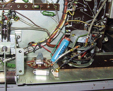
Much better
Martin
|
|
-
-
Dillen
- Joined on 02-14-2007
- Copenhagen / Denmark
- Posts 5,008
|
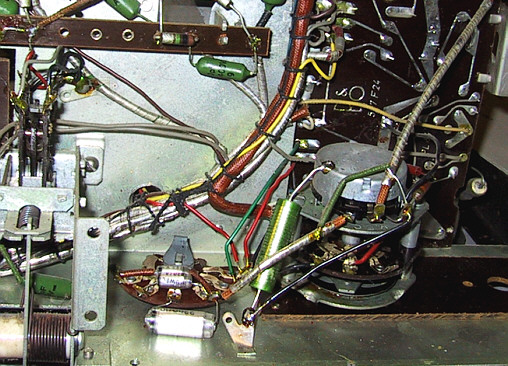
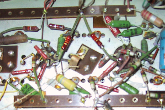
Right at the center of the chassis a small resistor looks a bit cooked. I would say beyond 'well done'.
I cannot read its color coding anymore and I doubt it to be still OK.
Another one nearby looks a little dark too.
Martin
|
|
-
-
Dillen
- Joined on 02-14-2007
- Copenhagen / Denmark
- Posts 5,008
|
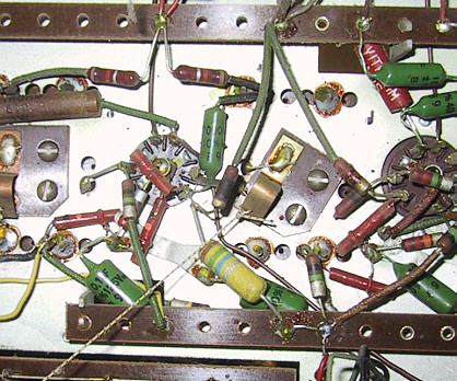
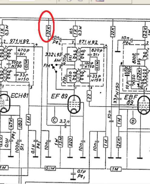
The manual gives this resistor as a 22Kohm and with a little good will I may be able to spot part
of the first red colored ring.
A quick in-circuit check gave a reading of apprx 50 Kohm which proves that this resistor is in need
of attention.
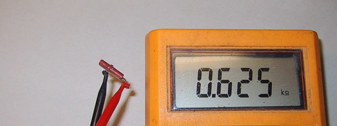
The meter reading out of circuit provided more proof:
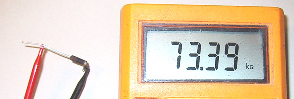
and here it is together with its replacement. I chose to upgrade slightly from a 1/4 Watt to a 1/2 Watt type.

The other resistor got the same treatment
Martin
|
|
-
-
Dillen
- Joined on 02-14-2007
- Copenhagen / Denmark
- Posts 5,008
|
But I still need to find out why that resistor got toasted.
The schematics show the resistor (red circle) feeding a grid on the EF89 valve.
Martin
|
|
-
-
-
Dillen
- Joined on 02-14-2007
- Copenhagen / Denmark
- Posts 5,008
|
Thanks Peter.
It's nice to know that there are people who actually read all of this. 
The birds nest build is a very simple and cheap way of constructing but not always
easy to repair.
It may at first glance seem easy to work with but:
- Leads and connections can hide behind other things.
- You will often have to take out one or two other components to reach a third.
-You will have to document everything as you go, there are no hints to component connections.
- A wrongly connected component does not stand out.
- Neither does a missing.
- You can easily do heat damage to components and leads when soldering deep into the nest.
- Replacing f.e. a valve socket usually means an hours work and lots of notes.
- Even large components can sometimes be difficult to find because they may not sit right
where you'd expect but instead they are found another place where the same connections
just happen to be in a suitable mutual distance for the component to bridge. Or it's found on the other side of the chassis.
- Some components or leads that work closely together may be deliberately placed far apart to avoid interference etc..
- Tracking connections is so much different from working with a PCB.
- Photo documentation will have to be from several angles and may yet still not be completely covering.
- Unused valve socket pins etc. are often used as a connecting point for components in a completely different part of the circuit. That can be very confusing at times.
PCBs are so much easier.
But hey, if it was twice as easy, it wouldn't be half the fun.
Martin
|
|
-
-
-
Dillen
- Joined on 02-14-2007
- Copenhagen / Denmark
- Posts 5,008
|
Thanks.
Great to know that I'm not just talking to myself here. 
Now back to that toasted resistor;
If this resistor conducts a too high current, it will be because it sees a too low resistance to ground somewhere.
Candidate components are :
- The 10nF capacitor that goes to the anode feed of the tuned circuit (it's a nice green Philips type so not likely to fail)
- The EF89 valve (it should then have a grid short - not very likely)
- The 3,3nF capacitor that goes to the cathode, having only a 220 ohm resistor to ground (this is a tiny tubular
ceramic capacitor so highly unlikely to fail).
- Further down a 15Mohm resistor is in series with whatever comes down there so that will not be the one to focus on.
Unfortunately, this leaves us without an obvious fault candidate but clearly something must be wrong here
so on with the meter.
A quick reading with an ohmmeter showed some 800 ohms from the grid to ground, which is far from right.
This is a fairly high impedance circuit so 800 ohms to ground will kill all programme sound.
The set will be quiet, maybe emitting only a faint humming.
We will have to look deeper into this:
- Resistors don't fail short so the 15 Mohm resistor can be ruled out.
- The valve is easily unplugged, it was confirmed that the 800 ohms were still measured in the circuit so
that rules out the valve.
- The 10nF capacitor is a foil type and it could theoretically fail short but nothing in the circuit at the other end
of that capacitor could provide such a low resistance to ground. That would have to be an anode/cathode short
in the valve but that never happens. Besides, that would require two faulty components at the same time
and the valve was already ruled out.
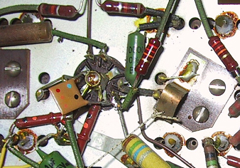
- The whole circuit is very simple and nothing is physically hidden, it's all in plain view underneath the chassis
so a short consisting of a broken wire, a stray cut component pin or the likes can be ruled out too.
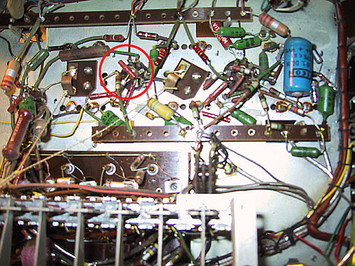
- This leaves us with only one component. The least likely of them all, the tubular ceramic 3,3nF capacitor.
This type of capacitor is generally seen as being one of the most reliable components on planet earth.
A ceramic component will usually only become defective if physically broken or one of its leads fall off.
In other words, if it fails it will almost always go open circuit. A capacitor of this nature will never short.
This particular one looks absolutely fine. No signs of physical damage whatsoever.
This is the one (red circle):
Martin
|
|
-
-
Rich
 
 - Joined on 07-10-2010
- Orlando, Florida, USA
- Posts 1,089

|
 Dillen: Dillen:Great to know that I'm not just talking to myself here.
Also listening.....
Current primary listening: SMMC20EN -> BG4002 -> BM4000 -> Beovox M70
|
|
-
-
Dillen
- Joined on 02-14-2007
- Copenhagen / Denmark
- Posts 5,008
|
Putting the ohmmeter across the capacitor gave a reading of apprx 600 ohms.
Hmm... it has a 200 Ohm resistor to ground at the other end... that could easily add up to 800 ohms...
One lead from the capacitor was lifted away from the circuit and the capacitor was measured again.
Same result. 600 ohms across.
That is wrong. Very wrong !
Out it came and it was measured one more time :
Martin
|
|
-
-
Friedmett
 
- Joined on 04-28-2007
- Herning, Denmark
- Posts 840

|
Also listning along with members of my personal Danish B&O thread on another forum. 
Its always a treat to see any of these kind of threads.
|
|
-
-
Dillen
- Joined on 02-14-2007
- Copenhagen / Denmark
- Posts 5,008
|
Thanks Anders, greatly appreciated ! 
This kind of fault is extremely rare.
The tubular capacitor consist of a ceramic tube with silver coatings inside and outside with a lead
connected to each coating.
How on earth this can change into a resistor is beyond me but it has happened here.
Now I know why the 22Kohm resistor got toasted.
Ohms law used in this circuit gives a power dissipation of apprx 2 Watts in the 22Kohm resistor.
No wonder this 1/4 Watt resistor quit the job.
No doubt this fault is what caused the set to be taken out of service many years ago.
It will have smelled badly and smoke will have been emitted.
The set will also have turned silent at the same time or a few seconds before.
A fresh ceramic capacitor made things right here. I found a nice NOS vintage component
that won't look out of place in this set.
Martin
|
|
-
-
Søren Mexico

- Joined on 09-13-2007
- Mexico city
- Posts 1,621
|
For amateuers like me this is listen and learn, I bookmark Martins threads.
Beosound 3000, BL 4000, BL 8000, BG 2404,BG 5000, BG CD50, Beocord 5000, BM 901, BM 2400, BM 4000, BV S45, BV 3702. There is nothing we cannot do, but a lot of things we don't want to do!!
|
|
-
-
-
Dillen
- Joined on 02-14-2007
- Copenhagen / Denmark
- Posts 5,008
|
Thanks. 
That was one more fault found and cured.
And I still haven't had any power to the set.
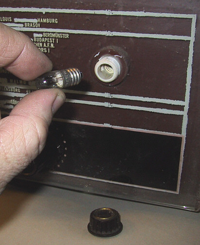
Speaking of mains power, the dial lamps will be the first and clearest indicators of power when the set is
switched on so I like them to work.
Being in series with the valve heaters, they will also tell me if the heater chain is OK.
The lamps measured fine but both had blackened glass envelopes so fresh lamps were fitted.
The original lamps were 6,3V 300mA E10 which was pretty much a european standard at the time but
I like to fit 7V lamps instead. If the set is used on 220V, it may give a slightly dimmer light on the dial but
it will also provide a much longer lamp life and the valve heaters will be ever so slightly underrun, also extending
valve life.
Another thing is that now we have 230V in the mains outlets in Denmark (222-226V in my little
repairshop) it makes sense to upgrade the lamps voltage a bit.
The dial lamps are easily replaced.
It's a 2-minute job - for doing both.
Martin
|
|
-
-
Dillen
- Joined on 02-14-2007
- Copenhagen / Denmark
- Posts 5,008
|
All knobs and buttons were then cleaned and the knob brights polished a bit.
One knob, the tuning knob, had rusted to its spindle and its grub screw wouldn't budge.
I gave it a drop of sewing machine oil and left it to soak in overnight.
Next day the knob was easily losened and I can even reuse the grub screw.
The knob itself had an old break that was badly glued.
I cracked it open a bit, injected a little superglue and pressed it back to shape.
I then filled the hollow knob from the backside with 2-comp. epoxy glue. That will
strengthen the whole knob and it will be useable again.
The glue line is at the side with the screw so I will use this knob for one of the tonecontrols
since they only work within a few degrees of rotation and always has the screw facing
downwards, out of view.
The dial glass was cleaned on the outside.
I really would like to clean the inside too but with lettering of this type, it's generally not a good idea.
The lettering will almost certainly come off and the dial would be ruined so I will leave it alone.
A few more measurements, a check of the filter and reservoir capacitors and a couple of other things
and the chassis was now ready for the first powering up in decades.
Workbench cleared, multimeters attached to a couple of strategic points and the sets mains cord
connected to the variac.
Slowly, the voltage was brought up while keeping an eye on the current meter.
Everything looked fine.
The dial lamps lighted up and the valves started glowing.
The current meter did the usual step-up suggesting that the output valve had warmed up enough to start
conducting current.
Everything looked fine. The well-known faint smell of warm dust, nothing more.
Power down.
Its own speakers are still in the cabinet so a test-speaker was connected and about half a meter of test
lead was fitted to the FM antenna socket.
Power up again.
Warmed up nicely again, a little humming, a sudden loud burst of sound, I think it was music of some sort
and then silence.
I touched the volume control and got another loud burst of sound.
Power down.
The volume potentiometer was then cleaned and exercised a bit.
It's very common to see a bit of oxidation, dust and dirt etc. in potentiometers and contacts
in radios that stood unused for years so that came as no surprise.
The pushbutton contacts got a shot of contact cleaner as well and the set was powered up again.
And away it went as if it had never failed.
With a couple of multimeters still attached, it played along for about half an hour.
All wavebands were tested and all gave plenty of stations, apart from shortwave but that
seems to be normal for my geographic location.
Longwave picks up noise from nearby energy-saving lightbulbs as usual and FM provides good signal strength
and lots of stations on just that half a meter of lead.
The dial calibration is almost spot on, I won't touch any of the alignments.
This will end up a good performer, no doubt.
The chassis is almost ready, it's only missing the tonecontrol knob that was glued earlier.
This knob cannot be fitted when the chassis is in the cabinet so I will have to wait for the epoxy to fully set.
It's glowing now, Mika. You know the pleasant warm smell.
Martin
|
|
-
-
Dillen
- Joined on 02-14-2007
- Copenhagen / Denmark
- Posts 5,008
|
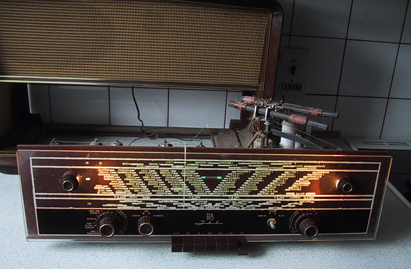
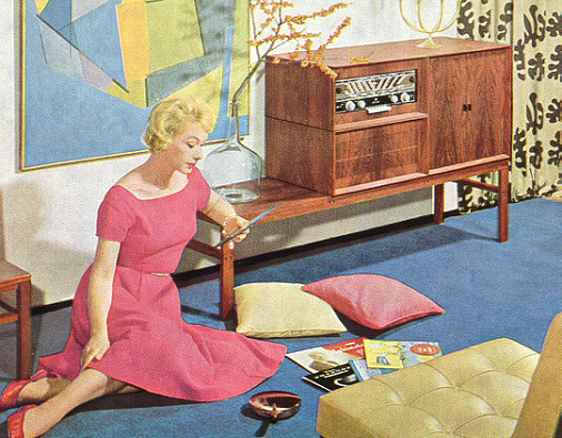
Note the fairly slim height of this chassis. The same chassis was available in a much lower cabinet
with no built-in speaker as part of the then super modern building furniture series.
The considerably lower cabinet volume in the building furniture series dictated the need for
a capacitive dropper rather than the large ceramic resistor for adapting mains to the lower voltage
needed for the heater chain but the rest of the chassis is basically the same.
The speaker was then placed in a separate cabinet of the same dimensions and other modular
building blocks would contain the record player, TV, tape recorder, records, tapes etc.
Martin
|
|
-
-
-
-
jrantala
  - Joined on 01-29-2011
- Finland
- Posts 53

|
Martin,
Your restoration "diaries" are absolutely superb! They are really useful lessons in vintage equipment repair, and pictures are always very nice and incormative. Even the flow of the stories is... should I say, very entertaining!
Please give us more...more...MORE!!
-jari
|
|
-
-
Søren Mexico
- Joined on 09-13-2007
- Mexico city
- Posts 1,621
|
jrantala:
Martin,
Your restoration "diaries" are absolutely superb! They are really useful lessons in vintage equipment repair, and pictures are always very nice and incormative. Even the flow of the stories is... should I say, very entertaining!
Please give us more...more...MORE!!
-jari
There is an old German saying that describes it "der Laie staunt und der Fachman wundert Sich" someone may be able to translate
Beosound 3000, BL 4000, BL 8000, BG 2404,BG 5000, BG CD50, Beocord 5000, BM 901, BM 2400, BM 4000, BV S45, BV 3702. There is nothing we cannot do, but a lot of things we don't want to do!!
|
|
-
-
Eugene
  - Joined on 12-17-2008
- Posts 589
|
Dillen:
The size of the JET 606 is apprx. 60x38x28 cm so quite a large tabletop set.
Can you think of a more appropriate radio to have at that time than a JET set ?
Martin
Plug a turntable into it and you could listen to this.

|
|
-
-
Søren Mexico
- Joined on 09-13-2007
- Mexico city
- Posts 1,621
|
Perfect
Beosound 3000, BL 4000, BL 8000, BG 2404,BG 5000, BG CD50, Beocord 5000, BM 901, BM 2400, BM 4000, BV S45, BV 3702. There is nothing we cannot do, but a lot of things we don't want to do!!
|
|
-
-
Dillen
- Joined on 02-14-2007
- Copenhagen / Denmark
- Posts 5,008
|
Wow yes, that would be appropriate.
The now empty cabinet got a once-over with a little polish to make it shine again.
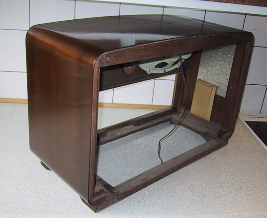
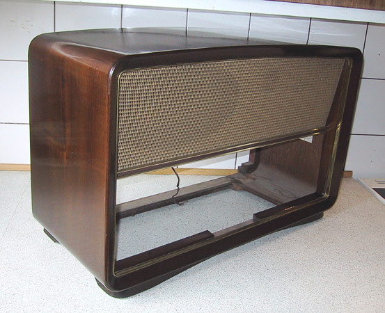
Martin
|
|
-
|
|
|