|
Untitled Page
ARCHIVED FORUM -- April 2007 to March 2012
READ ONLY FORUM
This is the first Archived Forum which was active between 17th April 2007 and
1st March February 2012
Latest post 11-27-2010 11:35 PM by Søren Mexico. 103 replies.
-
 08-27-2009 11:20 AM
|
|
-
 Dillen
  - Joined on 02-14-2007
- Copenhagen / Denmark
- Posts 5,008

|
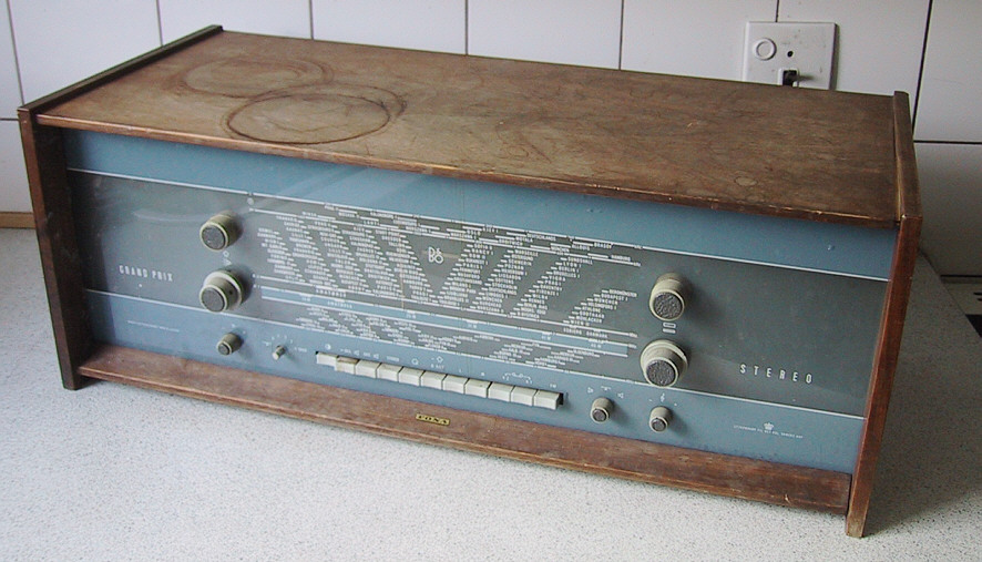
Grand Prix Moderne Stereo 609 - now with EK 4
Time for a little restoration write-up again.
The wonderful Grand Prix Moderne Stereo 609 was always one of my
own favourites (among many others...) and I have a couple of them in
my collection waiting for restoration but time has not yet permitted much
to that effect.
However, a couple of years back I came across the one pictured in this post.
Looking a bit sorry for itself and I bought it more or less with the
thought in mind that it could hold many valueable parts for the others when
their time comes. Locating set-specific parts can be difficult, especially when
it comes to the old valve things.
The other day I rediscovered it and gave it a closer look. At first glance
not the prettiest sight but on the other hand not the worst either and it
seems to be typical for me to try to save as many B&O's as possible and following
that track, I decided to give this one a chance of a second life.
I will update this thread as work progresses and as time allows.
Let's see how far this will come.
Martin
|
|
-
-
 j0hnbarker
  - Joined on 04-16-2007
- LS28/GB
- Posts 2,002

|
Re: Grand Prix Moderne Stereo 609
Looking forward to this one Martin! As the owner of one of the stars of a previous restoration thread, I can vouch for how entertaining they are!
What is the 'FONA' badge in the middle of the bottom of the fascia for, BTW??
President, Beomaster 8000 Appreciation Society
|
|
-
-
 Medogsfat
 
 - Joined on 02-21-2007
- *Moderator* Leeds, Yorkshire
- Posts 4,045

|
Re: Grand Prix Moderne Stereo 609
Was this one of the first ever B&O in car entertainment systems with integrated cup holders Martin?
Looking forward to this one and don't forget where I am if I can help at all.
Chris.
The use of metaphors should be avoided like the plague. They're like a red rag to a bull to me.
|
|
-
-
-
 Dillen
  - Joined on 02-14-2007
- Copenhagen / Denmark
- Posts 5,008

|
Re: Grand Prix Moderne Stereo 609
Thanks guys, very reassuring to know I have backup from you. 
This set, being a Grand Prix, was top notch at its time.
Built in 1962-63, its circuits and build quality was close to the max of what was possible
for a livingroom set back then and it's a superb performer when setup and serviced properly.
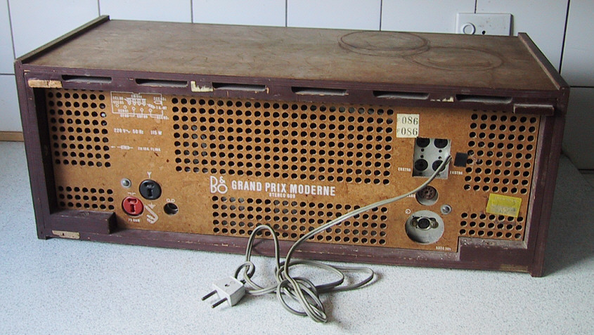
The owner had a choice of AM (LW/MW/SW) with a built-in AM antenna and FM
(requiring an external antenna) with the option of stereo in
the form of an extra module to build in. DIN plugs at the back are provided to
connect a turntable and a taperecorder, suggesting that the Grand Prix was meant
to be the center piece of what would potentially have been a quite impressive
sound system.
The Grand Prix supports an optional external echo-unit. This was probably mainly
a fashion-thing, only lasting a couple of years and I don't really see the
point myself, unless trying to achieve a "broader" hall-like sound.
Actually the so called echo-unit is more like a reverb unit but that's another story.
Not to my liking anyways and not many echo units exists, suggesting that it, not
surprisingly, wasn't a huge success. A (valve-type) socket is provided for
the echo unit at the back just below the 4 DIN speaker sockets (2 pairs).
A vast amount of controls are available and still it's easy to navigate and
use on a daily basis.
The top two round knob-like things are dial lamp holders which also holds the
dial glass in place.
The dial glass is actually perspex and very light so it sits firmly, held in
place only by those two holders.
The holder caps screw off and the dial lamp pops out, making dial lamp replacement
a 10-second job.
The next pair of round knobs have separate inner and outer knobs.
The left one has the outer portion functioning as the volume control and
the inner portion rotates the built-in AM ferrite antenna.
To the right, the tuning knobs, inner portion is for FM, tuning on the lower
part of the dial and outer portion controls AM with it's separate dial pointer
on the upper part of the dial.
The little round knobs on the bottom row are from left to right:
Bass, echo-amount(and echo off), balance and treble.
The push-buttons from left to right are:
OFF, Speakers 1, Speakers 2, Stereo, Turntable, AFC/Antenna, LW, MW, SW1, SW2 and FM.
Pressing both SW-buttons at the same time selects Tape.
Tuning is childs play.
The AFC control switch is also provided as a function on the tuning knob in that
pushing inwards on any portion of the knob (at FM tuning), switches off AFC
while tuning and back on again when the knob is released.
The "magic eye" tuning valve with it's distinct green bar will help you find the
best signal point and the AFC will help keep it.
All very fine but what have we got to work with then ?
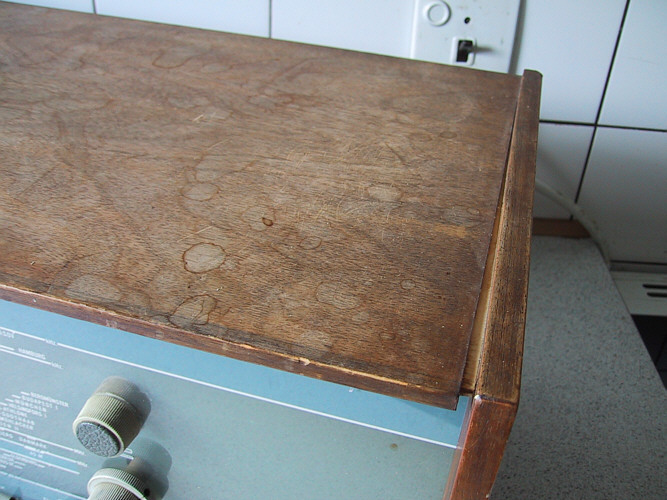
Bad things are that the cabinet is showing signs of a life in the basement, serving
as a platform for cans with fluids, paint or the likes. It also has some water-stains
and a split along its right side.
Apart from this, the cabinet is largely unmarked and I wouldn't be surprised if
it could be brought back nicely even if it will probably never break completely
free from its history.
A knob is missing. This type of knob was used heavily on B&O's TV's and radios
in those years and still they can prove hard to find. I don't see it as a huge problem though, at least
not for the time being.
The FONA decal, because that's what it is, was put on by the dealer.
FONA is a large chain of radio dealers in Denmark, they have been around for ages
and actually just recently stopped selling B&O.
I enjoy preserving labels and decals like this whenever possible but
this particular decal is not as nice as it looks in the photo and it would be
very hard, if not impossible, to restore the cabinet while preserving the decal
so I'm afraid it will have to go. Not being something B&O intended in
the first place, I have no problem accepting that.
Good things are that the rest of the set seems to be fairly intact. The dial is
unmarked, an important factor, and the back and bottom covers are both
present with the odd, almost mandatory missing, screw.
The mains flex is the original standard figure-of-eight type, looking safe and sound.
Thanks for your kind offer Chris, it may come in very handy as it did last time.
It would have to be a huge car to fit this fancy "cup holder with integrated radio"
in the dashboard, for sure. Not really portable either, no remote control and
I'm sure, it wouldn't know what to do if shown an mp3-file. 
Martin
|
|
-
-
 burantek
  - Joined on 05-04-2007
- SE USA
- Posts 6,214

|
Re: Grand Prix Moderne Stereo 609
 from me too! from me too!
Always great to follow your threads as they develop!
SIDE NOTE: Your assistance back in in pre-BeoWorld days saved my bacon, and I will never forget it! It is why I shall remain a gold member on the new rev of the site! Thanks for everything you do! Now, back to the show! 
|
|
-
-
 RUDYV
RUDYV
  - Joined on 07-31-2008
- Belgium
- Posts 52

|
Re: Grand Prix Moderne Stereo 609
I'm also looking forward to a new restoration thread !!!!!
The restoration threads are my favorites.
Thanks for doing this, Martin.
Rudy
|
|
-
-
 Dillen
  - Joined on 02-14-2007
- Copenhagen / Denmark
- Posts 5,008

|
Re: Grand Prix Moderne Stereo 609
Thanks Jaff and Rudy. 
There's almost always two types of faults in a restoration candidate like this;
- The original fault.
The fault that caused the set to be taken out of service and parked in the
attic or cellar because it was no longer doing what it was supposed to
and paying to have it serviced wasn't considered a feasible option.
This type of fault could be anything really, could be drastic so the repairers
quote was too high or as simple as a cracked solder joint that wasn't
even investigated.
It's also possible that the set didn't fail but merely got too old and was substituted
by a more modern model or it was simply no longer needed. My experience in these
matters has it that these situations are quite rare.
- Storage faults.
Faults that slowly develop with age and lack of use.
Capacitors spring to mind as candidates for this. They leak and dry out with age
and this will have to be corrected before applying power to the set for the first
time in decades.
Mechanical things will also seize up if not used regularly and, depending on the
storage conditions, rust and oxidation in switches, sockets and contacts will
also play a role.
No doubt, this set will have both types. Strange if it doesn't.
Martin
|
|
-
-
 Dillen
  - Joined on 02-14-2007
- Copenhagen / Denmark
- Posts 5,008

|
Re: Grand Prix Moderne Stereo 609
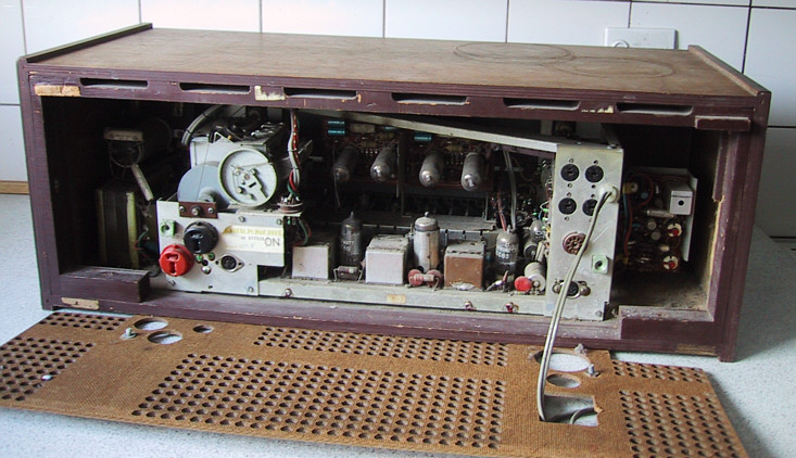
Off with the rear and bottom covers and let's have a look inside.
Looks fine with a nice layer of dust with no obvious signs of recent activity
(no wonder since I've owned it for a fair amount of years and haven't been
inside it before now).
Undisturbed is usually good in that most things are presumably present and in
their right places.
Indeed, it seems all valves and other major components are here.
Martin
|
|
-
-
 Dillen
  - Joined on 02-14-2007
- Copenhagen / Denmark
- Posts 5,008

|
Re: Grand Prix Moderne Stereo 609
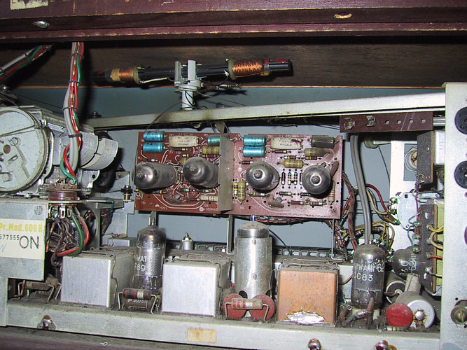
What a beauty, no less than 11 valves will be working in here - hopefully.
Having a closer look, I can already spot a couple of hours work now;
- The dial string for the rotating AM ferrite antenna has snapped. One end
of string is hanging down over the top metal chassis cross-bar, right by the two
left-most blue capacitors on the vertical amplifier board.
- In the bottom right corner is an aluminum can electrolytic capacitor that
obviously has leaked some of its contents. The brown'ish stuff has run down its
terminal and crept across the board a couple of centimeters.
- At the top right corner of the amplifier board, one of the blue capacitors is
not really blue anylonger. More like brown'ish black, suggesting that it
would like to be checked.
- Just to the right of the brown'ish capacitor, a fuse holder
sits - empty - on a piece of pertinax just below the top chassis cross-bar.
Its holding clamps heavily oxidated and bent outwards, unable to hold a fuse.
Already a good evenings work lined up.
Wonderful ! 
The power supply has its own chassis to the extreme left (as seen from behind).
A cable of wires run to a (valve-type) socket just to the right of the tuning
capacitor. This photo shows the above mentioned issues plus the power supply cable coming
down from a holding post at the underside of the cabinet top. Very service friendly.
Martin
|
|
-
-
 Dillen
  - Joined on 02-14-2007
- Copenhagen / Denmark
- Posts 5,008

|
Re: Grand Prix Moderne Stereo 609
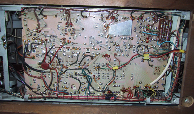
Underside view.
Everything looks fine down here.
No cracked solder joints, no burned PCB tracks, stray leads or similar.
Very nice.
Martin
|
|
-
-
 Dillen
  - Joined on 02-14-2007
- Copenhagen / Denmark
- Posts 5,008

|
Re: Grand Prix Moderne Stereo 609
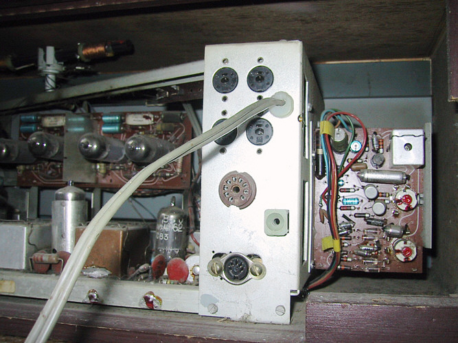
Hey, what's that ?
- I don't believe it !
This finding alone confirms that the decision of restoring this set was right !
Martin
|
|
-
-
 tournedos
  - Joined on 12-08-2007
- Finland
- Posts 5,808

|
Re: Grand Prix Moderne Stereo 609
 Dillen: Dillen:
Hey, what's that ?
- I don't believe it !
This finding alone confirms that the decision of restoring this set was right !
A solid-state MPX decoder? 
|
|
-
-
 Dillen
  - Joined on 02-14-2007
- Copenhagen / Denmark
- Posts 5,008

|
Re: Grand Prix Moderne Stereo 609
Exactly ! 
Finding a transistor based stereo decoder in an (otherwise) all-valve set is
quite amazing.
It clearly shows us which way B&O (and the world for that matter) was going
at the time.
The decoder is a PCB board of the same size as the ones known from Beomaster 900/1000
and circuit-wise not unlike it at all.
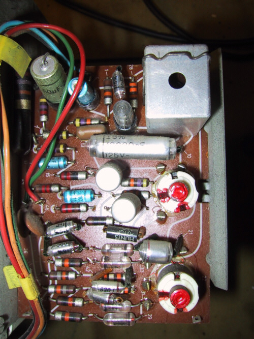
There's no socket provided for easy installation of the decoder and no
mentioning of it in the servicemanual so it was a surprise to find it
here and I can hardly wait to hear what this thing can do.
It sits in a specially designed metal bracket, bolted to the chassis.
A cable tree runs from the decoder to the sets main PCB board where the
individual wires are soldered "here and there", suggesting that the
Grand Prix was not actually prepared for a stereo decoder but one could be mounted
by an authorized serviceshop at a, presumably, fairly high cost.

Martin
|
|
-
-
 Dillen
  - Joined on 02-14-2007
- Copenhagen / Denmark
- Posts 5,008

|
Re: Grand Prix Moderne Stereo 609
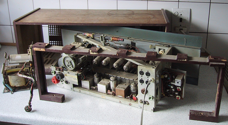
Now, let's get this thing apart.
A wooden frame goes around the top and down the sides, inside the cabinet.
Held by a good handful of screws of no less than three different lengths,
it blocks the way out for the two chassis'. It's visible in this photo,
in front of the main chassis, complete with dial and all knobs and
the power supply chassis at the extreme left.
Quite service friendly !
Martin
|
|
-
-
-
 Dillen
  - Joined on 02-14-2007
- Copenhagen / Denmark
- Posts 5,008

|
Re: Grand Prix Moderne Stereo 609
Andy, yes and no. There are several possible scenarios.
The clamps of the empty holder are extremely easily bent, almost brittle, so they could have given way
by themselves, simply losening their grip of the fuse.
If this is indeed what has happened, the fuse would still be somewhere inside the set, which it isn't.
The fuse could have found a way out of the cabinet if the set was moved about but it is not very likely
in that it would have fallen down between large components on the board and it would have required the set to be turned
upside down and rotated to rattle the fuse around and eventually get it out.
If the fuse indeed blew and a previous owner tried to fix it, he probably struggled with the fuse holder and at some
point, he'd given up - or the new fuse also blew and he got tired of it.
Or the fuse was the suspected culprit of a completely different fault. Or ...
Possibilities are many.
Anyway, I will have to measure around a bit to see if I can find any obvious faults that could have caused the fuse to blow.
This could be the "original fault" as described above, the reason for the set to be taken out of daily use.
I'm not worried, more excited to look into it. 
Martin
|
|
-
-
 Dillen
  - Joined on 02-14-2007
- Copenhagen / Denmark
- Posts 5,008

|
Re: Grand Prix Moderne Stereo 609
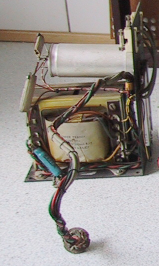
The power supply chassis is first on the bench.
It holds the mains transformer, the rectifier which is of the flat metal
type mounted on the rear vertical side, two fuses for the valve heaters and
filter and reservoir capacitors (built together into one can) as well as the
associated ceramic filter resistors.
Martin
|
|
-
-
 Dillen
  - Joined on 02-14-2007
- Copenhagen / Denmark
- Posts 5,008

|
Re: Grand Prix Moderne Stereo 609
The chassis seems to be in good condition but there IS some work to do;
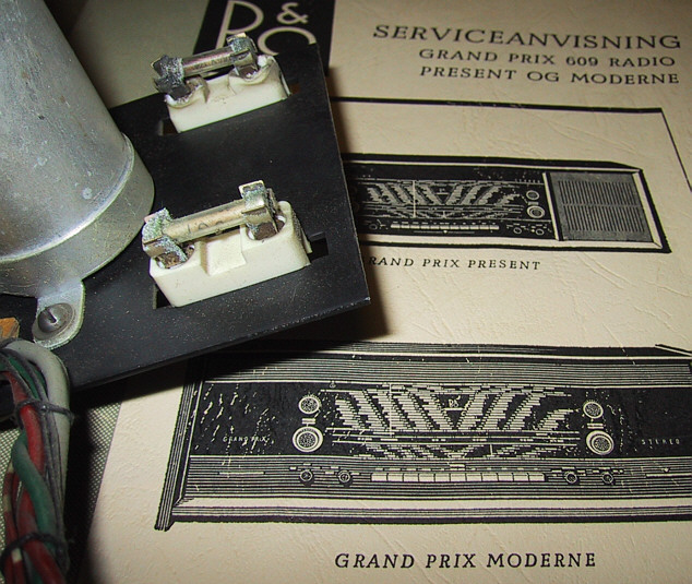
The two fuses look very sorry for themselves, let alone their holders.
Both suffer drastically from oxidation and one fuse holder has even melted a bit.
Not really visible in the photos, but the filter/reservoir capacitor is
quite domed upwards from the end with the solder tags.
This is a sign of overpressure inside the can and at this point I'm happy that
I didn't power anything up without checking a couple of things first.
If this capacitor had exploded, it would have been a terrific experience and
there's a good chance it would have left the set with no option for a restoration or
at least a huge job cleaning up the mess.
I will mount two new capacitors of a modern type to take over the job while
leaving the original one in situ for appearance and for an eventual future
restorer to hollow out and house new caps inside.
The oxidated fuses can be seen here.
These are 10A fuses, and even if they don't pass 10A at all times, any bad contact
here will undoubtedly develop heat.
Martin
|
|
-
-
 Dillen
  - Joined on 02-14-2007
- Copenhagen / Denmark
- Posts 5,008

|
Re: Grand Prix Moderne Stereo 609
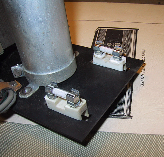
The fuse holders were taken apart and new clamps were mounted.
The clamps came from a modern PCB-solder type fuse holder that had suitable
clamps for these holders.
The melted holder was ground down using a small file and cleaned off all
dirt and soot. A slight discoloration is all that's left of its former misery.
It's always very satisfying when a thing can be repaired rather than replaced.
Now, much better.
Martin
|
|
-
-
 Dillen
  - Joined on 02-14-2007
- Copenhagen / Denmark
- Posts 5,008

|
Re: Grand Prix Moderne Stereo 609
Working with the power supply chassis, I notice how it flexes under the weight of the
large transformer. The vertical part of the chassis, that holds the filter
capacitor and fuses will "twang" a couple of degrees to both sides.
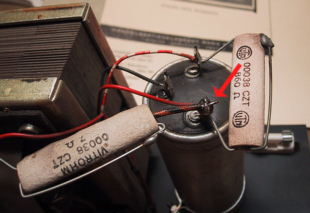
This puts a lot of stress on the large 7 ohm ceramic filter resistor,
visible to the left in this photo. It has one end soldered to a tag on
the transformer and the other to a tag on the capacitor, building a "bridge"
between the two. This has caused the solder joint at the capacitor end
to let go, allowing the very rigid resistor pin to slide in and out
through the tag and the joint (red arrow) as the chassis flexes and bends.
Obviously a design flaw and we will have to do something about it.
This photo also shows a little better, the way the cap has "domed".
Martin
|
|
-
-
 yachadm
 
 - Joined on 06-24-2007
- Jerusalem, Israel
- Posts 687

|
Re: Grand Prix Moderne Stereo 609
Hi Martin,
Nice job! I always like to see restorations!
If you need any capacitors or tubes, let me know - I have a good selection of tubes from the same era, for restorations I have done on Saba and Grundig radios of the 1950's.
Or any other parts you have trouble finding, at all!
Nice to see the MPX - the 19kHz and 38kHz coils look in good shape, but check those carbon resistors - on 2 similar units I did, that PCB was a major rebuild.
Do you have a good local carpenter who can restore the cabinet? I was very lucky to find a dedicated carpenter here, who works magic with the old tube-radio cabinets. If the stains and chips are beyond repair, you can have the carpenter sand off 1mm of the old veneer, and apply a new veneer layer on top, followed by a proper woodstain and polyurethane coating.
Menahem
Learn from the mistakes of others - you'll not live long enough to make them all yourself!
|
|
-
-
 Dillen
  - Joined on 02-14-2007
- Copenhagen / Denmark
- Posts 5,008

|
Re: Grand Prix Moderne Stereo 609
Menahem, thanks for your ideas, inputs and kind offers.
I have most of the valves used in this set in stock myself as NOS parts plus
a nice selection of good used valves and other parts from scrapped sets so
I think, I'll be fine. But thanks anyway, very kind of you and I'll keep it in mind.
Only thing missing at present is a knob but I will solve that, I'm sure.
Setting the goal is important in every restoration.
It's always a decision to make how much to restore or replace and how
much to keep.
I would like to see this one as a "sensible" restoration
and by that I mean, I will be aiming at restoring and repairing while keeping
as much as possible original, using most of what's present in the set and
also let the set keep it's identity and history.
I am not trying to make a new set - or just a new looking set but
rather a set that was used, loved, stored and restored. And of course it should be
working and safe to use on a daily basis.
The power supply chassis fuse holders are very good examples of this strategy;
I can buy new holders but it wouldn't feel right for this job.
Instead, new clamps were mounted and the original holders were worked a bit
to make them good and safe again.
In the same manner, the MPX decoder will have to prove defective or far
out of spec before eventually attacking it. Anyway, the resistors would not be
my first concern but rather those AF116/117/118 transistors used here.
These transistors have a tendency to develop internal shorts by growing
conductive hairs from the inside of their metal shells to the junction and
inside connections but that's a completely different story that we can take if
it comes up. Besides, none of the resistors on the MPX board work with high
voltages so will not be specifically prone to going high in value.
Of course, the board and its functionality will be checked.
Any faults will be cleared but I won't replace every component on sight
just for the sake of replacing. If the old components are still OK, they
have proved their reliability and will stay.
Little marks of normal use will be OK but of course I will try to remove most
of the water stains and rings on top but I will not refinish the whole set
even if I cannot remove all marks. Only if a substantial amount of marks,
scratches, dent or chips spoil the general appearance.
I have worked with veneer several times with fairly good results
and this set couldn't be more square and easy to re-veneer.
But re-finishing the set is not reversible and for me would be an absolute
last resort, finding a better original cabinet being the better alternative
but let's first see how far it will go as-is.
A polyurethane coating would be very far from original for this set
as would any other lacquer finish.
Maybe I will have to use a selection of chemicals and other drastic methods
but a light grinding, palisander oil and a good polish would be my
first try, I think.
Martin
|
|
-
-
 Dillen
  - Joined on 02-14-2007
- Copenhagen / Denmark
- Posts 5,008

|
Re: Grand Prix Moderne Stereo 609
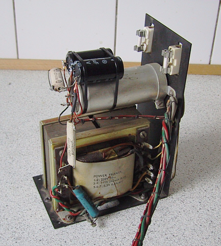
New high voltage capacitors has now been mounted.
Being too large to build into the original can, I decided to leave the can
in situ and instead fasten the two new caps using cable ties.
They are VERY stable here and this operation leaves no permanent marks and
is fully reversible when a future restorer have access to smaller components
that will fit inside the old capacitor housing.
The red arrow points to the joint that was previously a problem.
The rigid resistor pin has now been extended using flexible copper strands
to allow the vertical part of the chassis to flex back and forth without
stressing this high voltage joint.
And now allow me a couple of words about the two ceramic resistors;
They are both safety components, acting as "thermal fuses".
They each have one of their pins going through their hollow body and round
one end where it - just outside of the resistor - has a solder joint.
This solder joint has been made using a solder with a specific melting point
and should NOT be resoldered. They are supposed to look a bit grey and dull
and it's very tempting to redo them. But DON'T !
The soldered pin has a spring tension introduced from the factory and
when/if the resistor heats to a specified temperature, the solder
melts and the spring tension is released, breaking the continuity of
the component and in turn leaving the set powerless.
These joints are marked with green arrows in the photo below.

Martin
|
|
-
-
 Dillen
  - Joined on 02-14-2007
- Copenhagen / Denmark
- Posts 5,008

|
Re: Grand Prix Moderne Stereo 609
This concludes work on the power supply chassis, at least for now.
Martin
|
|
|
|
|