|
Untitled Page
ARCHIVED FORUM -- April 2007 to March 2012
READ ONLY FORUM
This is the first Archived Forum which was active between 17th April 2007 and
1st March February 2012
Latest post 10-25-2009 10:03 PM by MAKEDONIA. 141 replies.
-
-
-
 Dillen
  - Joined on 02-14-2007
- Copenhagen / Denmark
- Posts 5,008

|
Friedmett wrote : "Will you remove the added bits to keep it more original or
will it be best to still keep it in?"
- I don't know if any of the added parts work at all but I will try to remove
the added parts if possible.
I would prefer even a not-original dial lamp to that huge resistor anytime
and the added mains filter cap is also nasty, it doesn't belong there so
hopefully I can do away with it.
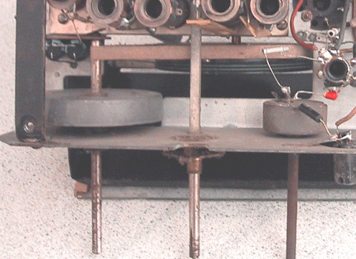
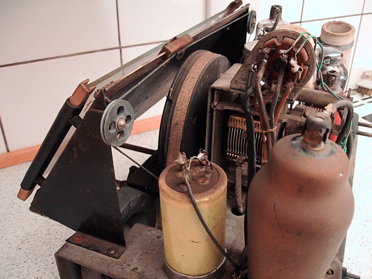
Andy wrote : "...the dial cord has stood the test of time (if it's original) What's it made of, metal?"
- No metal. Around the 6mm tuning knob shaft is an apprx 10mm wide linen band
that goes to the large tuning capacitor pulley, that's the white'ish looking
band visible in the photo, running in the widest of the two grooves in the
large pulley. You can also see it running down a cutout in the pulley, it goes
down to a spring that keeps it tight. The linen band feels slightly abrasive and
seems to have a very good grip on the tuning knob shaft.
The other groove (nearest to the dial) carries a standard dial string that
drives the dial pointer, this string looks and feels incredibly solid and
the whole mechanism works very convincing. I don't think any of it
will cause problems.
Thanks for bringing this up. In many old radios the dial string arrangement
will indeed provide for many hours of entertainment.
This is what it looks like from the other side (dial face down) :
Martin
|
|
-
-
 PWH
PWH
  - Joined on 06-22-2008
- Posts 44

|
Hi Dillen, If you need parts, I have most of them including valves. Do you have a diagram? I can probably find something very similar. www.vintage-radio-resources.com Regards
|
|
-
-
 Dillen
  - Joined on 02-14-2007
- Copenhagen / Denmark
- Posts 5,008

|
Hi PWH, Thanks for this nice link. Actually, I had it bookmarked already.  Yes, I have the large B&O compendium and also all but a few of the
original discrete service manuals but thanks for your generous offer.
It's very true that even if you cannot find the schematics for a certain valve set,
you will be able to make out most of it by looking at a contemporary set using
the same valves. B&O's can, however, sometimes be a little tricky in certain
circuits, like this one's tonecontrol which is quite complex, and
the correct schematics is a must. Luckily, I have the full service manual for this one. Regarding parts, I have most in stock myself but of course when restoring
something like this you always stock up and prepare for everything and still
end up missing one or more parts you never imagined you'd need so I may take you
up on the offer.
You don't happen to have a dial lamp or the missing knob ? Martin
|
|
-
-
 Dillen
  - Joined on 02-14-2007
- Copenhagen / Denmark
- Posts 5,008

|
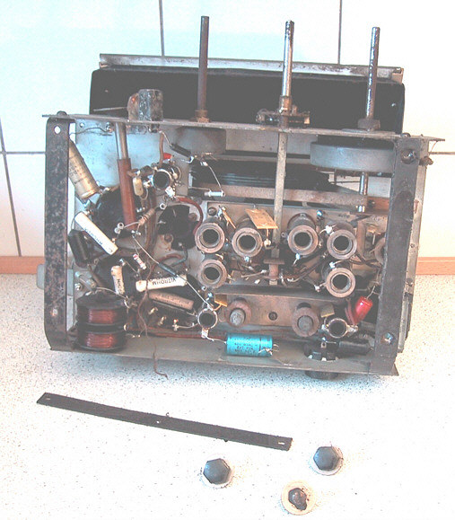
The volume potentiometer is missing alright. Only the metal tube used for the
push/pull mains switch and the mains switch itself is present, the latter being
well past its best days in that it's completely frozen.
At least one ceramic capacitor sits with one lead flying in open space, presumably
in need of a tag on a volume potentiometer to connect to.
At first glance it looks like this radio hasn't been seriously got-at though
some things definitely has happened in here, especially around the now missing
volume control potentiometer and dial lamp.
The service manual will have to shed some light on this and I may even have to
dig out my own Beolit 39 to compare circuits and components.
Martin
|
|
-
-
 Dillen
  - Joined on 02-14-2007
- Copenhagen / Denmark
- Posts 5,008

|
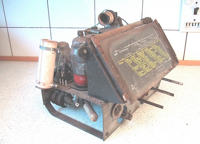
The majority of the original leads used in this radio is of the type with
rubber insulation. This type of insulation is known to become brittle and crack over
the years, leaving the wires inside bare to short to eachother or whatever comes around.
Even leads with fine looking insulation will often crumble to pieces when touched.
Looking at the chassis, it's very clear that especially the leads passing
through areas with high working temperatures, near the power resistors and
the leads that go to the top caps of the tubes have suffered. Some so bad, I cannot
tell what color they were.
Many leads will have to be replaced in this radio as a matter of safety.
All in all a good restoration project. Nowhere near the everyday two-hour job
but I wasn't expecting it to be either.
Martin
|
|
-
-
 PWH
PWH
  - Joined on 06-22-2008
- Posts 44

|
you wrote>The bad things are that the lettering on the dial has more or less gone and what's left is almost unreadable, this is something that will have to be solved somehow. If you have a good dial, scan it and print onto clear film then make a 'sandwich' with 2 thin pieces of glass. If you don't have another dial, many hours with photoshop then do the above Good Luck! I think you will be able to remove the base from a new bulb & fix it to the old connector. I expect it was 1 bulb which was a bit brighter/dimmer depending on what voltage selection was used. I don't have that base, but may have correct shape & wattage. Regards
|
|
-
-
-
 Dillen
  - Joined on 02-14-2007
- Copenhagen / Denmark
- Posts 5,008

|
Thanks for the tip about the dial.
I have made a couple of other dials this way. Some even involving
laserprinter water-transfers and the results were very good.
However, the problem with this particular set is that large parts
of the dial lettering is in white and, apart from serigraphic
machines, it is practically impossible to print white on clear.
The dial lamp base contains a couple of built-in interconnects for
the mains voltage setting function so at least the base will be reused.
The lamp itself is listed as 110V 200mA for this model, so
a replacement shouldn't be too hard to come by.
Thanks also for the note about safety. I already mentioned it a couple of times
and it really cannot be stressed enough.
Restoring old radios (let alone TV's) should be a fun hobby so please do take
care. DC voltages of 300 Volts or more is to be expected and respected.
When working on a powered chassis, always keep one hand on your back.
Don't feel tempted to hold or support the chassis with one hand while
working with the other; If the chassis isn't live and kills you right
away, there's a true risk that you will inadvertently touch some high
tension somewhere inside the set and cause a current track to chassis through you.
This particular set has a power switch that simply goes directly to chassis so
when powered off there will be no live. Still, the capacitors can hold a
lethal voltage so there's no excuse for slacking caution.
You're right, I will probably not power up the radio for yet some days.
I've come down with pneumonia so I haven't been able to continue work
on the set but it has given me some time to scrutinize the service manual etc.
and plan actions.
Martin
|
|
-
-
 PWH
PWH
  - Joined on 06-22-2008
- Posts 44

|
Hi Dillen you wrote> it is practically impossible to print white on clear. Yes, but sometimes you can take a clear waterslide shape and spray it white, then print the transfer, the white comes out clear. Put the white on first and the 'clear' on top so you have a transfer on the transfer. The white will come through Takes a bit of practice, does not work on all patterms. but may be possible. Regards
|
|
-
-
-
-
 Craig
Craig
 
 - Joined on 03-29-2007
- Costa Del St Evenage
- Posts 4,855

|
Hope you feeling well soon Martin. Craig
For millions of years, mankind lived just like the animals. Then
something happened which unleashed the power of our imagination. We
learned to talk and we learned to listen..
|
|
-
-
 rayfenwick
 
 - Joined on 04-28-2007
- Hull UK (again)
- Posts 693

|
Yes, hope you're feeling better soon Martin - we're all itching for the next installment ;)
Ray
Я люблю Банг и Oлуфсен
|
|
-
-
-
 Dillen
  - Joined on 02-14-2007
- Copenhagen / Denmark
- Posts 5,008

|
Thanks for all your health wishes and the nice card. Very warming 
I am very much looking forward to continue work on this set but that will have
to wait a couple more days, I'm afraid.
However, I can report on a couple of minor things I managed to attend
before I went down: The object, that was rattling inside, turned out to be an apprx 19cm long and 12mm
wide flat black metal plate with two holes in it (visible in photo b10 above). At present it's not clear to
me where it fits in but from the amount of dust and light surface rust on it, I'd
say it looks pretty much the radios age.
Maybe my own Beolit 39 will provide more information. The dial pointer has lost most of its cream color paint but what's more serious, it's
scraping against the backside of the dial at the leftmost 7-8 cm of its travel.
This is where most of the dial lettering is missing.
Doh ! [:'(]
The pointer is only supported at the top where it slides on felt pads on the
edge of a fairly thick and strong metal plate which seems to have been bent slightly.
A dented corner on a mounting bracket near one corner of the dial glass also
suggested that the chassis was once dropped or at least had a severe bang on that
particular corner.
Using pliers, the slider plate was gently bent back to make sure that the pointer
will never touch the dial again.
The dial pointer now travels nicely across the dial but the mechanism makes a
whining noise. A little drop of sewing-machine oil to a couple of dry spots cured this. Next thing will be to dig out my own Beolit 39 to compare circuits and components. Martin
|
|
-
-
 Craig
Craig
 
 - Joined on 03-29-2007
- Costa Del St Evenage
- Posts 4,855

|
Should be good to see a picture of the two chassis side by side. Craig
For millions of years, mankind lived just like the animals. Then
something happened which unleashed the power of our imagination. We
learned to talk and we learned to listen..
|
|
-
-
 Dillen
  - Joined on 02-14-2007
- Copenhagen / Denmark
- Posts 5,008

|
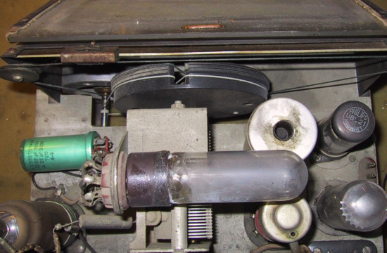
Well, back on track and eager to move on so today I took apart my own
Beolit 39 (chassis no 45105) to compare circuits and components.
It seems that my Beolit 39 is pretty much original apart from a few things;
One dropper resistor has been replaced at some point, now sitting on a tag strip
fastened under one of the nuts on the IF can's screws, looks a very neat job and
since this component will emit a vast amount of heat when the radio is on, the new
position is definitely better than the original.
The resistor, originally one 2W component, is now converted into three 4W
ceramic resistors in parallel so that will lessen the heat dissipation even more.
Also the mains smoothing and filter cap(s) looks newer than what I would expect
to find and also here the replacement has been mounted very neatly. The cap mounted
here is of a different type than whats mounted in the other set and it has been
mounted horizontal rather than vertical.
The output valve has been changed from the original CBL1 to a UBL21 using a
socket converter. Many sets in Denmark had their output valves removed during WW2
and it may have proved hard to find an "old" CBL1 after the war and instead
a "modern" U-series valve was fitted. If's that is indeed the reason, or it was
simply cheaper, I suppose noone will know for sure, but it's my guess.
Martin
|
|
-
-
 Dillen
  - Joined on 02-14-2007
- Copenhagen / Denmark
- Posts 5,008

|
These are all repairs that are legal in my opinion, since they were performed while
the radio was still in daily use and it was done to keep the radio going.
Noone imagined that it would still be around today and if it wasn't for the
above repairs, it probably wouldn't have been.
Any repairs done to the radio today, now beeing a collectors piece, will have to
be done with a lot more respect to originality. I will do my best to do all
my repairs with this in mind, preferably also reversible so an eventual future
restorer won't have to face problems that I've caused but I won't compromise when
it comes to safety and usability.
I want this radio to work and do that safely.
Comparing the two chassis' left me with an idea of the type of potentiometer used
for the volume control, same type as the one used for the tonecontrol it appears,
and it also confirmed my thoughts regarding the modified circuit in that the
volume control, now missing, has simply been bypassed so that the radio, if working
at all, would constantly play at maximum volume (!). Surely not an optimal situation.
Furthermore, it was also confirmed that the large ceramic resistor, that has been
mounted to a little metal bracket bolted to the chassis near the speaker socket, is
not original. It has been introduced as a replacement for the broken
dial lamp, in series with the valve heaters.
A note was found in my own set, telling that the resistance of the dial lamp in
warm condition is apprx 105 ohms. Why they measured this beats me.
The new resistor seems to be apprx 600 ohms so is obviously out of place here if
the note can be trusted. This is something I will have to find out.
Opening my own set, however, didn't provide any further info regarding the stray
metal plate. I didn't find anything like it in my own set.
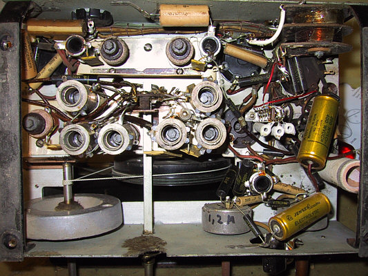
Martin
|
|
-
-
 Jandyt
 
 - Joined on 04-01-2007
- Clitheroe, Lancashire, UK
- Posts 13,004

|
 Dillen: Dillen:
I will do my best to do all
my repairs --- so an eventual future
restorer won't have to face problems that I've caused
Martin
I have to admire you for this statement Martin.
Obviously, the person who left you the little note, so many years ago, was a kindred spirit!
The dial bulb is a lot bigger than I was expecting.
|
|
-
-
 Dillen
  - Joined on 02-14-2007
- Copenhagen / Denmark
- Posts 5,008

|
Thanks Andy, but it's quite true actually.
There's really nothing more annoying than finding out that you
could have fixed a certain fault if it hadn't been for a previous repairers
failed attempt.
Like in this set with the potentiometer missing. If it was still in the set,
albeit defective, I could have used it as a reference or maybe even repaired it.
The repairer would have had no use for it anywhere anyways so could just as
well have left it in there.
If I, god forbid, for some reason will have to give up on this repair, I will
include all info, maybe a printout of this thread, inside the set for
the eventual next repairer.
Anyway, I will have to find a replacement volume potentiometer before I can go much
further and in the meantime I will turn my attention to other issues, starting
with the speaker.
The speaker sits on its own little chassis, held by two screws from the bottom of-
and four screws inside the cabinet.
The two screws underneath are of the same type as those used to hold the
main chassis and both of these have their bakelite heads still intact.
Since the speaker chassis will never be the bearer of live mains and the
main chassis definitely will be, I will use the screws with intact insulating
heads for the main chassis and the others for mounting the speaker.
The radio doesn't have any rubber feet, felt stickers or the likes. It simply
stands on its six bakelite screw heads so I will have to put something on the
heads where the bakelite is missing if I can't locate two original bakelite covered
mounting screws.
Wrapped in a cloth bag with a closing string, the speaker assembly is safe from
dirt and dust that would otherwise accumulate inside the speaker and eventually
distort the sound or simply block the voice-coil.
Now, the dust and dirt has instead accumulated on the cloth in front of the speaker
and looks like a nice mix of dust, dead spiders, larvae coccoons, moths vings etc.
Some 70 years of history is gathered here, daily life and tragedy.
No recently dead insects though and even woodworm is no threat to a bakelite radio.
The assembly was taken outside for a well deserved cleaning and it was confirmed that
the stray metal plate, that I found under the main chassis, was not a part of
the speaker assembly either.
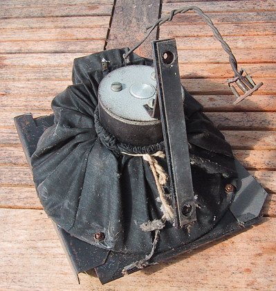
Martin
|
|
-
-
 Dillen
  - Joined on 02-14-2007
- Copenhagen / Denmark
- Posts 5,008

|
The speaker chassis also carries the output transformer.
Connecting an ohm-meter across the transformer primary tags, protruding
through the cloth, gave a good reading and I could hear the speaker produce little
cracks of sound when I connected and disconnected the meter. The first selfmade
sounds from the speaker for years.
Little crackling sounds may not sound very impressive to the reader but to me it
is very good news in that it confirms that both the speaker and transformer
are working, at least enough to test them further.
In the workshop a B&O TG7 signal generator was connected to the output transformer
primary winding. The speaker itself is on the secondary winding and of a much
lower impedance.
The set 1kHz gradually became more and more audible as the output level of the TG7
was increased and when the signal generator reached it's max output of apprx 3Vrms
the sound from the speaker was clear and bright. A brief frequency sweep up and down
revealed no audible distortion or rattling.
Further testing of the speaker assembly will have to take place using radio
programme sound so will have to wait a bit longer.
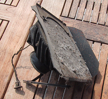
Martin
|
|
-
-
 Dillen
  - Joined on 02-14-2007
- Copenhagen / Denmark
- Posts 5,008

|
The cabinet is now empty.
Only the speaker grill and dial frame are still attached and
I see no reason why they should be removed so to minimize the risk of damage
I will leave them in situ, wipe all remaining dust and dirt out and store the cabinet
safely in the box in which the radio arrived, wrapped in towels.
Waiting for a suitable volume potentiometer gives me time to take a closer look
at some minor issues on the chassis;
The first thing I will attend is the leads with crumbled insulation.
We don't want to power up anything that looks like this.
Three valves have top caps and all three wires going to the top caps have
crumbled insulation. Under the chassis are several short stumps of leads going
between valves and other components, most are crumbled though not as serious
as the ones going to the top caps.
Some will definitely need replacing, though.
I have found a few feet of high temp cable, originally used during WW2 for rocket
launchers or the likes. It has a silicone insulation that my trusted Weller
temperature controlled soldering iron won't even mark at it's highest setting.
It leaves but a slight discoloration if anything at all.
This will be ideal for using here. Picture shows before and after.
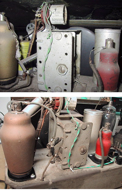
Martin
|
|
-
-
 Craig
Craig
 
 - Joined on 03-29-2007
- Costa Del St Evenage
- Posts 4,855

|
Really hope you can find a potentiometer for this set Martin. Craig
For millions of years, mankind lived just like the animals. Then
something happened which unleashed the power of our imagination. We
learned to talk and we learned to listen..
|
|
-
-
 Dillen
  - Joined on 02-14-2007
- Copenhagen / Denmark
- Posts 5,008

|
Thanks Craig. Yes, that would indeed be nice, sadly 1Mohm potentiometers
with a built-in push-pull mains switch are no longer off-the-shelf parts
but I won't give up without a fight.
While the search goes on, I will turn my attention towards the rest of
the chassis again, there's lots of work to be done here.
Both the main smoothing cap and the cap that was obviously added during
a previous repair measured far from specs so something will have to be done here.
The two 24uF sections measured at 16uF and 42uF respectively. Furthermore, both
were found to be leaky, proving that the caps are slowly but certainly turning
into resistors.
One section measured as low as a few kiloohms and that was the section of
the dual-cap that was still in circuit !
Caps growing in capacitance is bad. The capacitance meter measures under very
low load conditions and when a cap is measured high on the meter, it will
most certainly fail under load, maybe even short.
Caps lose their "tension" somewhat comparable to an elastic band; It dries out
with age. Using only a little force you can pull it longer than what it was
originally but there's little chance it will pull itself correctly back together
again when you let go. Pull harder and it snaps.
The voltage on these caps with valves warmed up is given as 208 Volts in the
service sheet but before the valves are warm, especially the output valve which
counts for the majority of the current used, the voltage can easily be
more than 300 Volts.
I don't dare to think what would have happened if the radio was simply plugged
in and switched on.
A high voltage electrolytic capacitor explosion is nothing I can recommend and
inside this little beauty ? - No thanks.
Leaning more and more towards the theory of the yellow cap being the original, I
will remove the added un-original cap and leave the original cap in
situ for appearance.
It will, however, not be electrically connected. Instead I will try to find
room for two new 22uF 400V components somewhere under the chassis, out of normal view.
Physically, the modern components are only a fraction of their late 1930's equivalent.
Martin
|
|
|
|
|