|
Untitled Page
ARCHIVED FORUM -- April 2007 to March 2012
READ ONLY FORUM
This is the first Archived Forum which was active between 17th April 2007 and
1st March February 2012
Latest post 11-05-2011 9:28 PM by Andre. 72 replies.
-
-
 Søren Mexico
 
 - Joined on 09-13-2007
- Mexico city
- Posts 1,621

|
Re: BeoGram 4000 Restoration
 yachadm: yachadm:Is it possible that 4IC1 is at fault - FCH131 - holy cow, where to find one? Normally those were very reliable, but one never knows.
I searched the web for IC FCH131 and found several suppliers and prices from USD 20-50.00
Beosound 3000, BL 4000, BL 8000, BG 2404,BG 5000, BG CD50, Beocord 5000, BM 901, BM 2400, BM 4000, BV S45, BV 3702. There is nothing we cannot do, but a lot of things we don't want to do!!
|
|
-
-
hemenex
 
- Joined on 04-23-2007
- Posts 375

|
Re: BeoGram 4000 Restoration
Menahem,
I had a deep look into the SM of the BG4000 today. I never have seen one in real life, though.
First, it should be totally ok to use a DVM to measure motor voltage - Why would MOhms parallel to a low-ohm DC coil cause a wrong measure?
As the circuit is a servo bridge and the servo runs ok while playing (if I'm right?) in the slow forward / reverse (FO / RE?) 4IC1 is just an ordinary inverter (with internal pull-ups and -downs of course). You should be able to measure if the input changes to high on e.g. FO at pin3 of IC1. Output should switch to 0 then. Same vice-versa. An ordinary transistor with the corresponding PU/PD resistors and the diodes should do as well. This IC isn't highly integrated (didn't mika mention that BTW?). But it isn't absolutely genuine anymore then...
All this is purely theory - can't verify if that's correct 
My old book that I bought for my study tells me input PU's were 5k, output PU's 2k. Base PD is 5k. Can post a picture of DTL's internal circuitry if that helps.
On Board 3 the FCH131's are much more trickyly used - although mainly as Flip-Flops.
Had a look at my deepest basement but sorry - never had any DTL circuits. Started with bare 7400, no S, LS, L...types.
Good luck,
Gunther
|
|
-
-
Søren Hammer

- Joined on 01-07-2008
- Esbjerg/Denmark
- Posts 554
|
Re: BeoGram 4000 Restoration
It could be a little tricky to find some of those old logic curcuits, but as Søren said, the FCH131 apparently still is available after over four decades of production, the BC547 of DTL's? 
It's quite strange that the pickup leads were soldered in reverse, never heard about flaw like that though!
Beocenter 9300, Beogam CD50, Beocord 5500, Beomaster 3400, Beomaster 4400, 2 Beogram 4000, Beomaster 8000, 2 beogram 8002, Beovox S-75, Beovox MS150.2, Beovox RL6000, Beovox S-35, Beomaster 6000, 2 Beocord 9000, Beocord 8004, Beocord 5000, Form 1, 2x Beolink 1000, Beo4, MX3500, LS4500. Born 1993.
|
|
-
-
yachadm
 
- Joined on 06-24-2007
- Jerusalem, Israel
- Posts 687

|
Re: BeoGram 4000 Restoration
Gunther,
Thank you! Yes, the FCH is before my time as well. I DO have < and > functions - it just runs fast, because the voltage is at about 10VDC, instead of about 3VDC.
And the Potis are brand-new Bourns Cermet units - the ones I use for many years now- excellent quality, so they are not at fault.
So I am just trying to figure out why they are not adjusting the voltage.
I have the datasheet of the FCH131, with the pinouts, and they are pulling high and low on schedule, so it's a little confusing here.
With a bit of perseverance, some light is bound to illuminate the dark recesses.....
Menahem
Learn from the mistakes of others - you'll not live long enough to make them all yourself!
|
|
-
-
yachadm
- Joined on 06-24-2007
- Jerusalem, Israel
- Posts 687
|
Re: BeoGram 4000 Restoration
Søren Hammer:
It's quite strange that the pickup leads were soldered in reverse, never heard about flaw like that though!
Yes, how many times does a tech check polarity of the 4 colored tonearm wires?
We just take it for granted that they're OK, as long as we hear something playing through the amplifier in both channels, right?
To be honest, in all the BeoGrams I've serviced, I never checked that once. Just this one time, I thought to check them, and there you are!
Undocumented service changes, and incorrect Service Manuals - I've already found a few, and it's not serious - I can generally find my way around without a manual - in most B&O vintage stuff - the technical design is really quite consistent, and always a pleasure to work on.
But a production mistake - yes, that's quite rare.
You've also got a BG4000 - did you check yours?
Menahem
Learn from the mistakes of others - you'll not live long enough to make them all yourself!
|
|
-
-
chartz
 
- Joined on 07-20-2009
- Burgundy
- Posts 984
|
Re: BeoGram 4000 Restoration
yachadm:
You've also got a BG4000 - did you check yours?
Yes, Menahem!
Mine is actually the same as yours, same "mistake" then, but it doesn't affect the sound in any way...
I too thought some logic dinosaur was dead until I replaced the sensor arm lamp. After replacement, everything worked normally. The lamp is part of the logic!
I love my Beogram 4000! It has replaced my Beogram 8000, with the inconvenience of not being remote controlable!
So where are you now?
|
|
-
-
yachadm
- Joined on 06-24-2007
- Jerusalem, Israel
- Posts 687
|
Re: BeoGram 4000 Restoration
Aha! Your curiosity got the better of you!
So it was a production goof!
I'm not surprised that it is your #1 TT.
I'm waiting for capacitors and resistors. As soon as they arrive, I'll continue.
Learn from the mistakes of others - you'll not live long enough to make them all yourself!
|
|
-
-
yachadm
- Joined on 06-24-2007
- Jerusalem, Israel
- Posts 687
|
Re: BeoGram 4000 Restoration
Capacitors arrived.
Installed as in pic.
As always, for the skeptics who claim - "No reason to change capacitors - my 40-year-old BeoGram is working flawlessly".
Proof positive - the circuits are overstressed with excessive ripple.
Pictures below!

Learn from the mistakes of others - you'll not live long enough to make them all yourself!
|
|
-
-
yachadm
- Joined on 06-24-2007
- Jerusalem, Israel
- Posts 687
|
Re: BeoGram 4000 Restoration
This is the ripple on the 23.2V circuit with the large 3000uF original capacitor. Capacitance measured 3565uF. Ripple 1900mV pp. 
Learn from the mistakes of others - you'll not live long enough to make them all yourself!
|
|
-
-
yachadm
- Joined on 06-24-2007
- Jerusalem, Israel
- Posts 687
|
Re: BeoGram 4000 Restoration
This is the ripple on the 23.2V circuit with the new 3900uF capacitor. Capacitance measured 3662uF. Ripple 1000mV pp. Similar results on all 4 circuits. 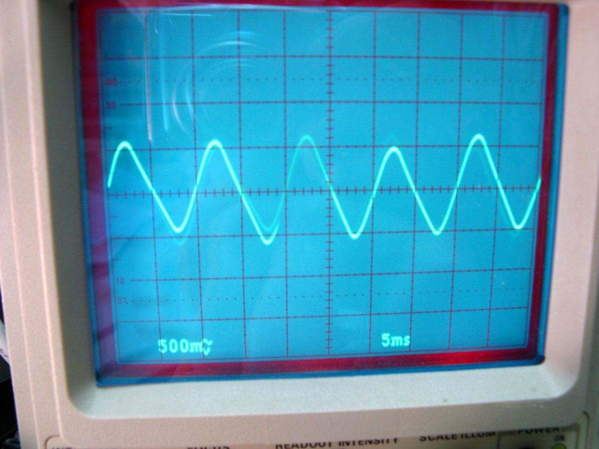
Learn from the mistakes of others - you'll not live long enough to make them all yourself!
|
|
-
-
Dillen
  - Joined on 02-14-2007
- Copenhagen / Denmark
- Posts 5,008
|
Re: BeoGram 4000 Restoration
Nice work.
We've generally had a lot of talk about replacing capacitors here on Beoworld but, as you suggest by
stating that some owners claim their old Beogram is still doing fine, maybe it would be interesting for
the readers, and those owners in particular, to know a little more about the background and motivation
for replacing those caps, like what works better and which circuits become less stressed by the new and
considerably larger caps, why the 900mV is so important etc.
And if I may suggest a bit of insulation on the leads that runs very close to the chassis metal.
Martin
|
|
-
-
yachadm
- Joined on 06-24-2007
- Jerusalem, Israel
- Posts 687
|
Re: BeoGram 4000 Restoration
Thanks for the compliment, Martin!
I did write a little article about this - it's on my website - here's the link.
How to Choose Replacement Capacitors and Resistors when Repairing and Restoring Vintage Stereo Equipment
This is a layman's explanation, with a fair bit of literary license!
Basically, the more linear / stable the power supply current, the cleaner the sound, and the longer-lasting the components.
In layman's terms, think of yourself as pushing a heavy wheelbarrow along a road.
Think of that road looking like the above ripple waveforms.
The less hilly the road, the easier the job you've got, and the less wear-and-tear on your muscles and the wheelbarrow. The less-tired and the more-refreshed you arrive at your destination.
On a more hilly/bumpy road, the more shaken up and exhausted you are, and the sooner your joints will give out, and the sooner we'll bury you.
It's the same with electronics. The length of life of any semiconductor (transistor/diode/IC - the expensive bits) is directly proportional to the stability quality of the current flowing through it, when the appliance is operating.
The capacitor is directly responsible for the quality of stability in those currents. The capacitor is like a Caterpillar grader that comes along onto that bumpy road, and grades out most of the bumps.
In effect, the capacitor takes on the task of absorbing the stresses, in order to give the semiconductors an easy life. That's as long as the capacitor is in good shape.
But in taking on and absorbing the stresses of the circuit, the capacitor itself breaks down - it sacrifices itself for the overall good.
Sooooo, that's why we replace all the (relatively cheap) capacitors during a restoration - to make sure that those expensive (now-unobtainable) semiconductors can keep functioning with stable current.
Learn from the mistakes of others - you'll not live long enough to make them all yourself!
|
|
-
-
Søren Mexico
- Joined on 09-13-2007
- Mexico city
- Posts 1,621
|
Re: BeoGram 4000 Restoration
yachadm:
Thank you Menahem, I allways follow your threads, learning something new every time.
Beosound 3000, BL 4000, BL 8000, BG 2404,BG 5000, BG CD50, Beocord 5000, BM 901, BM 2400, BM 4000, BV S45, BV 3702. There is nothing we cannot do, but a lot of things we don't want to do!!
|
|
-
-
filip_kbh
  - Joined on 05-15-2011
- Posts 46
|
Re: BeoGram 4000 Restoration
I am trying to adjust the tracking force but no matter how I adjust the screw on the back, I can't get more than approx. 0.90 grams when the adjustment wheel shows 1,5. I am going for 1,2 for my MMC20EN cartridge but that is not possible. What should I do? I have tried adjusting it as it says in the service manual and the Beogram 4002-6000 restoration guide.
If the weight is too close to the arm, the arm won't lower :-(
I have lubricated all relevant parts.
|
|
-
-
yachadm
- Joined on 06-24-2007
- Jerusalem, Israel
- Posts 687
|
Re: BeoGram 4000 Restoration
Filip,
You need to move that vertical catch out of the way at the rear of the arm to do the ZeroBalance setup. The cartridge must be mounted when you do it.
Learn from the mistakes of others - you'll not live long enough to make them all yourself!
|
|
-
-
yachadm
- Joined on 06-24-2007
- Jerusalem, Israel
- Posts 687
|
Re: BeoGram 4000 Restoration
Almost all done - after replacing all the caps on the main PCB, and many out-of-spec resistors, it's almost working 100%.
EXCEPT for one thing - When pushing < (Forward), adjusting the poti does nothing. Motor Voltage remains at 12.5VDC. Rearward > works just fine - I've set it at 5VDC - the SM states 3V, but that's too slow.
There is one glaring discrepancy between the SM and the PCB.
1R42 is 270ohms installed, but 10KOhm in the SM. I have no Service Bulletin referring to that discrepancy. The pic shows 1R42 circled in white, but before I started work on the machine.
Martin, Jacques, Peter, can you all please check your actual PCB's, if it's not too much trouble, and see what you have actually installed? If you don't have the Service Manual, send me a PM and I'll send it to you.
Menahem 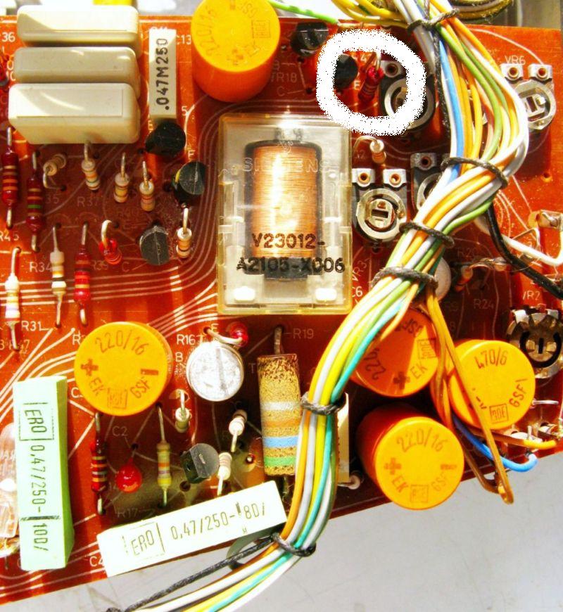
Learn from the mistakes of others - you'll not live long enough to make them all yourself!
|
|
-
-
chartz
- Joined on 07-20-2009
- Burgundy
- Posts 984
|
Re: BeoGram 4000 Restoration
Menahem,
My 4000 is assembled again, but I won't take it apart before one month when I change the big caps.
I wouldn't worry too much though, because we have late production decks and there are a few differences indeed. If the solder looks original then it should be okay. But since it seems that only the two of us have this particular model, information from other members possessing earlier models may not be relevant... Patience my friend!
|
|
-
-
Dillen
- Joined on 02-14-2007
- Copenhagen / Denmark
- Posts 5,008
|
Re: BeoGram 4000 Restoration
I don't have a BG4000 at hand right now.
1R42 is, if I'm not mistaken, in the (record-) sensor signal shaping circuit and
has nothing to do with the servo motor control.
The scope patterns shown in the schematics are the results of the lamp/sensor
looking at the radial streaks on the platter.
A resistor may be different from the schematics, that wouldn't be a first but unless it
looks unoriginal or "got at", I wouldn't worry too much about it.
Martin
EDIT: The two resistors (R20 and R24, I think) look as if they could be touching.
|
|
-
-
yachadm
- Joined on 06-24-2007
- Jerusalem, Israel
- Posts 687
|
Re: BeoGram 4000 Restoration
Movie time!
Functioning perfectly - I had to disassemble all the keyboard switches again, and add solder to the flappers to tension them - now the < and >, slow and fast speeds function perfectly.
Next up is the cosmetic restoration! Anyone know of a workshop which can build a new acrylic cover?
Learn from the mistakes of others - you'll not live long enough to make them all yourself!
|
|
-
-
chartz
- Joined on 07-20-2009
- Burgundy
- Posts 984
|
Re: BeoGram 4000 Restoration
Nice work Menahem!
Also nice to hear your voice!
In the next video, we'd like to see the platter and how the arm detection works! The noises your deck makes are the same as mine, with a noisier carriage motor than the earlier examples.
|
|
-
-
yachadm
- Joined on 06-24-2007
- Jerusalem, Israel
- Posts 687
|
Re: BeoGram 4000 Restoration
Until I understood how the < and > switches worked, this was very frustrating. Once I understood how they worked, it is obvious why B&O changed the design to separate << , < , > , >> buttons on the BG4002/4 and BG6000.
On this BG4000, the < or > , has 2 functions. It is not obvious from the schematic or the component diagram. One < button has the function of < , and <<.
If you look at the diagram below, it appears that the FF or FR switch has the NC (normally closed) and NO (normally open) positions - 2 separate circuits, which appears to be very simple.
The NC position is at rest, and the NO position is <<.
So where is the < position?
Answer - it is BETWEEN the NO and NC contacts, when the flapper is not touching anything. This requires only a very light press on the keyboard, and it is this which is most troublesome in adjusting.
Because the flappers had lost tension, it was impossible to get the flapper to remain stable in this small 1mm-wide space, to have a Slow-Forward speed.
After I had resoldered the entire length of the flapper, it was now stiff enough to be able to stabilise in the zero-contact area, which I adjusted now for about 3.5V, which gives a nice slower speed, but not too slow.
I can imagine the problems which B&O had on these buttons under warranty! 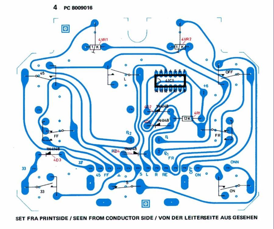
Learn from the mistakes of others - you'll not live long enough to make them all yourself!
|
|
-
-
chartz
- Joined on 07-20-2009
- Burgundy
- Posts 984
|
Re: BeoGram 4000 Restoration
Hi,
Same analysis here! However I did it differently - perhaps less elegantly - I added a spacer and it works just as well.
|
|
-
-
yachadm
- Joined on 06-24-2007
- Jerusalem, Israel
- Posts 687
|
Re: BeoGram 4000 Restoration
Yes, Jacques, that would also work nicely.
Martin, thanks for your pointers - the 2 resistors were actually not touching, but close, but anyway, that was the first picture I took when I opened the unit - I had not even cleaned it yet! But it was the only picture I had to post here! Now I have more pics!
Also, the leads on my new main capacitors are 12mm above the chassis, and very firm, so there is no danger to causing any shorts with the chassis, otherwise I would have used shrink-wrap. Also, I need that particular lead exposed, because it is the main ground-wire, so I have a solid earth point for measuring all circuits.
Now, here is the main PCB, completely redone - you can see that the potis are not present - I wanted to use the Bourns potis (not the Piher through-hole) here, and there was plenty of vertical access space on the print side of the PCB, so that's where they are!
And using Wima and Nichicon capacitors, and lots of Vishay-Dale CMF precision low-noise resistors to replace the out-of-spec ones. 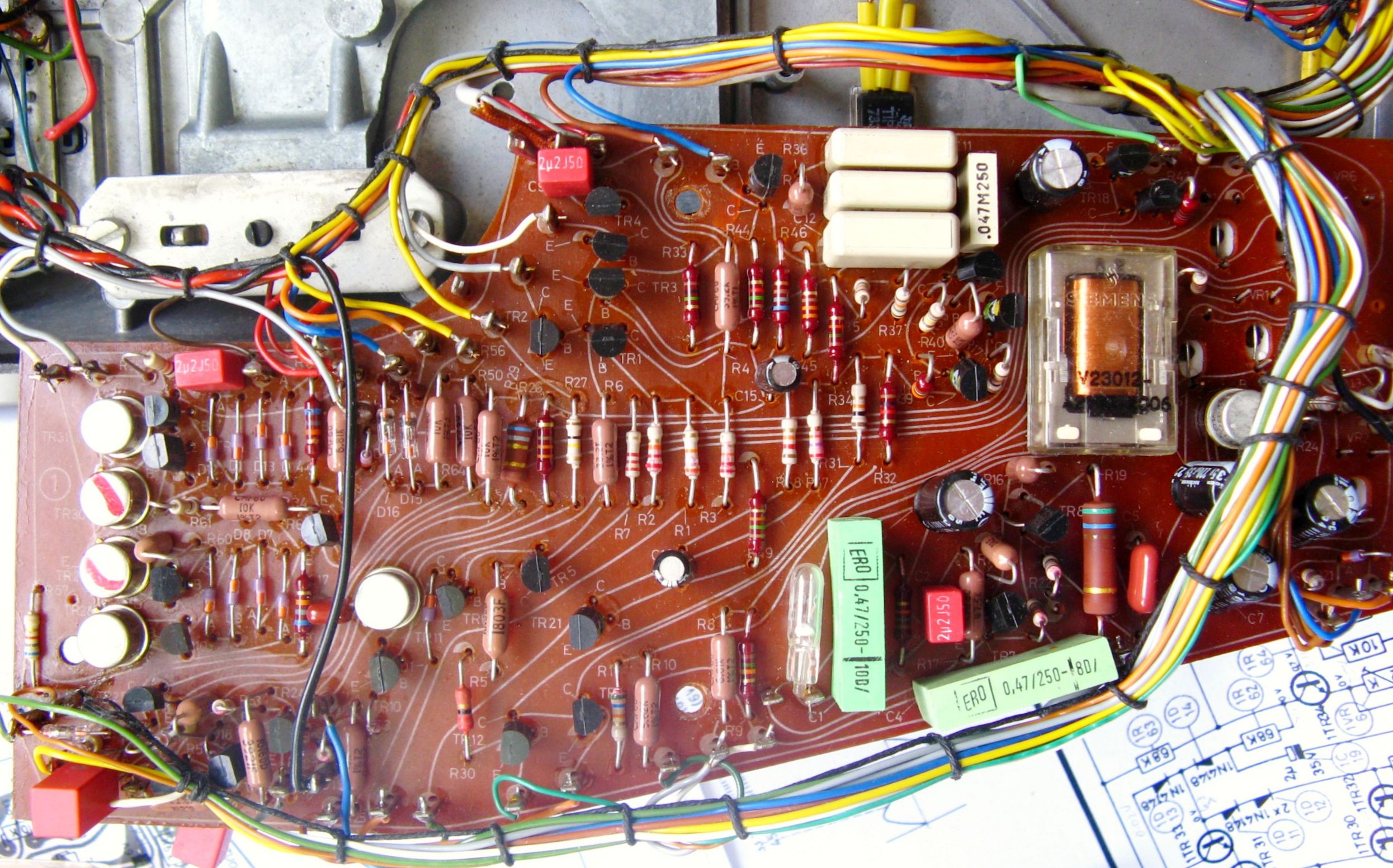
Learn from the mistakes of others - you'll not live long enough to make them all yourself!
|
|
-
-
filip_kbh
- Joined on 05-15-2011
- Posts 46
|
Re: BeoGram 4000 Restoration
yachadm:
Filip,
You need to move that vertical catch out of the way at the rear of the arm to do the ZeroBalance setup. The cartridge must be mounted when you do it.
Hi - yes, I know, and the cartridge is on and I do press down the vertical catch. Still nothing :-(
|
|
-
-
yachadm
- Joined on 06-24-2007
- Jerusalem, Israel
- Posts 687
|
Re: BeoGram 4000 Restoration
No, you must NOT press down the vertical catch ("C" in Section 3 of the BeoGram 4002 Guide), not at all. You must push it UP, and hold it UP all the time while you are balancing it.
Learn from the mistakes of others - you'll not live long enough to make them all yourself!
|
|
|
|
|