|
Untitled Page
ARCHIVED FORUM -- April 2007 to March 2012
READ ONLY FORUM
This is the first Archived Forum which was active between 17th April 2007 and
1st March February 2012
Latest post 11-05-2011 9:28 PM by Andre. 72 replies.
-
 08-31-2011 3:34 PM
|
|
-
 yachadm
 
 - Joined on 06-24-2007
- Jerusalem, Israel
- Posts 687

|
BeoGram 4000 Repair Restoration
Hi all,
I just picked up a throwaway Beogram 4000. Not in the best cosmetic shape - cracked acrylic cover, but the aluminium fascia isn't bad - should clean up nicely. It is not mechanically operational at all, and the MMC20S is minus the cantilever.
I've restored about 15 of the BG4002's and BG6000's, but this is the first time I've ever seen THE original tangential TT.
I've cleaned the interior, and I'll be starting on the capacitors, potis and replacing the OA90's with AA143 diodes. The usual degrease and reoiling ala the BG4002 series, and then I'll try a power on (via a series lamp) and see what happens - more to come.
Here's the interior.
Menahem 
Learn from the mistakes of others - you'll not live long enough to make them all yourself!
|
|
-
-
hemenex
 
- Joined on 04-23-2007
- Posts 375

|
Re: BeoGram 4000 Restoration
good gracious...
that's a box full of electrolytics spreaded all over 
|
|
-
-
Rich
 
- Joined on 07-11-2010
- Orlando, Florida, USA
- Posts 1,089

|
Re: BeoGram 4000 Restoration
Best of luck from an interested reader!
Current primary listening: SMMC20EN -> BG4002 -> BM4000 -> Beovox M70
|
|
-
-
Evan
 
- Joined on 12-15-2008
- Ohio | USA
- Posts 2,601
|
Re: BeoGram 4000 Restoration
 hemenex: hemenex:that's a box full of electrolytics spreaded all over
What he said!!
Have fun with this, looks like there's plenty to be had! 
|
|
-
-
Søren Mexico

- Joined on 09-13-2007
- Mexico city
- Posts 1,621
|
Re: BeoGram 4000 Restoration
OH OH expensive 3000 caps
Beosound 3000, BL 4000, BL 8000, BG 2404,BG 5000, BG CD50, Beocord 5000, BM 901, BM 2400, BM 4000, BV S45, BV 3702. There is nothing we cannot do, but a lot of things we don't want to do!!
|
|
-
-
Søren Hammer
- Joined on 01-07-2008
- Esbjerg/Denmark
- Posts 554
|
Re: BeoGram 4000 Restoration
That is indeed one big mouthful
Beocenter 9300, Beogam CD50, Beocord 5500, Beomaster 3400, Beomaster 4400, 2 Beogram 4000, Beomaster 8000, 2 beogram 8002, Beovox S-75, Beovox MS150.2, Beovox RL6000, Beovox S-35, Beomaster 6000, 2 Beocord 9000, Beocord 8004, Beocord 5000, Form 1, 2x Beolink 1000, Beo4, MX3500, LS4500. Born 1993.
|
|
-
-
hemenex
- Joined on 04-23-2007
- Posts 375
|
Re: BeoGram 4000 Restoration
Søren Mexico:
OH OH expensive 3000 caps
Probably not expensive but surely in a strange dimension - most of the available ones are much wider in diameter 
But lookin' at Menahem's BM3400 there's a very slim nichicon 1000/50 so I'm sure he'll find suitable substitutes.
Gunther
|
|
-
-
yachadm
- Joined on 06-24-2007
- Jerusalem, Israel
- Posts 687
|
Re: BeoGram 4000 Restoration
Yes, that extra 1000uF cap boosts the standard 470uF decoupling cap on the Bridge rectifier. Because I dumped the original B80C, and substituted my own homebrew 4x Schottky bridge, I was no longer limited to the maximum bypass capacitance of the original B80C bridge. So now, with about 1500uF bypass capacitance, the ripple is almost nothing. Of course, the improvement in sound is quite audible.
I'll do the same Schottky upgrade thing on this BG4000, and here, I'll use 3900uF 50V, 25mm diameter, but obviously the length will be much less.
Menahem
Learn from the mistakes of others - you'll not live long enough to make them all yourself!
|
|
-
-
chartz
 
- Joined on 07-20-2009
- Burgundy
- Posts 984
|
Re: BeoGram 4000 Restoration
Menahem,
I shall be watching this attentively (and of course provide my help should you need it!), since I also restored a Beogram 4000 not so long ago. I think I know it (and its caveats) inside out!
Cheers,
|
|
-
-
yachadm
- Joined on 06-24-2007
- Jerusalem, Israel
- Posts 687
|
Re: BeoGram 4000 Restoration
OK, I've done enough of the bad components to start troubleshooting.
I have some problems with the keyboard contact switches - the flappers of < and V are not working - I'll have to pull apart the keyboard, and adjust.
Jacques - I hope you made good notes when you did yours ;-)
1. What DC voltages (reference to GND) did you get at the BCE of both 0TR1 and 2TR6 - very easy - it's the voltages on the big capacitors and the zeners? I know what the SM shows - I want real-world voltages.
2. What are the actual 1VR1 to 1VR6 installed on your PCB - mine do not match the SM values, and I want to know if I can install the minmum values possible to get more precision adjustments?
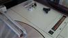
3. What is the DC voltage on the tonarm lamp sensor - I show 6.4Volts - lamp burnt out? I want to put in an LED, and discard the poti. See the picture - red arrow is the +ve supply to the lamp.

Learn from the mistakes of others - you'll not live long enough to make them all yourself!
|
|
-
-
Søren Hammer
- Joined on 01-07-2008
- Esbjerg/Denmark
- Posts 554
|
Re: BeoGram 4000 Restoration
I don't think that an LED puts out enough power to work with a photo sensor 
Beocenter 9300, Beogam CD50, Beocord 5500, Beomaster 3400, Beomaster 4400, 2 Beogram 4000, Beomaster 8000, 2 beogram 8002, Beovox S-75, Beovox MS150.2, Beovox RL6000, Beovox S-35, Beomaster 6000, 2 Beocord 9000, Beocord 8004, Beocord 5000, Form 1, 2x Beolink 1000, Beo4, MX3500, LS4500. Born 1993.
|
|
-
-
chartz
- Joined on 07-20-2009
- Burgundy
- Posts 984
|
Re: BeoGram 4000 Restoration
1. I have around 22V at 0TR1, and a little less than 6V at 2TR6.
2. I don't know.
3. Ditto a little less than 6V, obviously. On my BG 4000 the lamp was cut at its glass base.
A bad sensor lamp will affect the functions you mention. After replacing the lamp, these functions returned to normal.
As for the contacts themselves, they have a little red cap which can be wear out, and the height is wrong, thus obliging one to depress the flappers very hard!
|
|
-
-
yachadm
- Joined on 06-24-2007
- Jerusalem, Israel
- Posts 687
|
Re: BeoGram 4000 Restoration
Søren Hammer:
I don't think that an LED puts out enough power to work with a photo sensor
Soren, every BG4002/6000 I've restored, I have converted the photo sensor lamps to LED (15000-50000mcd) - the details are in my article - section 8.
B&O BeoGram 4002, 6000 Turntable Restoration Repair
In fact, in the later production 4002's (which by then were all DC-motors), B&O changed the production to include the LED as standard, instead of the lamp. I have not done a 4004, but I would presume that they all already had the LED's as standard by then, because they came after the 4002's.
I rough up the LED with sandpaper to diffuse the light in all directions. On this BG4000 circuit, I should need a only a 150ohm resistor to ground with 6.4 volts. If it doesn't work, I can always go back to the lamp!
So, that red cap, hey! I opened up the keyboard - no red caps - I have now put a ball of epoxy on each plunger - we'll see later if that solves the problem!
Menahem
Learn from the mistakes of others - you'll not live long enough to make them all yourself!
|
|
-
-
yachadm
- Joined on 06-24-2007
- Jerusalem, Israel
- Posts 687
|
Re: BeoGram 4000 Restoration
I now have all functions on the keyboard. I removed all the brass fittings, cleaned with contact cleaner, straightened the flappers, and resoldered everything. The epoxy balls on the plungers worked just fine.
LED done - works perfectly. Got rid of that ugly 100ohm poti. Made a new box to hold the LED, from a yellow plastic biro pen stem. See the pic - it's so bright, it even transmits through the black cover. The 150ohm dropping resistor is visible at the rear right - doesn't even get warm.
This is MUCH more sensitive than the 4002. Even after best adjustment, on the 4002, I'd see the servo motor rotate the worm axle about 3/4 of a turn each time. This is rotating only about 1/4 turn each time, and much more often. That means that the stylus is barely becoming "untangential", before correction by the phototransistor - I love it!
Next step - see if the super-dim 33 and 45 lights can be converted to LED's - sometimes on these circuits they work, sometimes not. Sometimes I have to be creative! 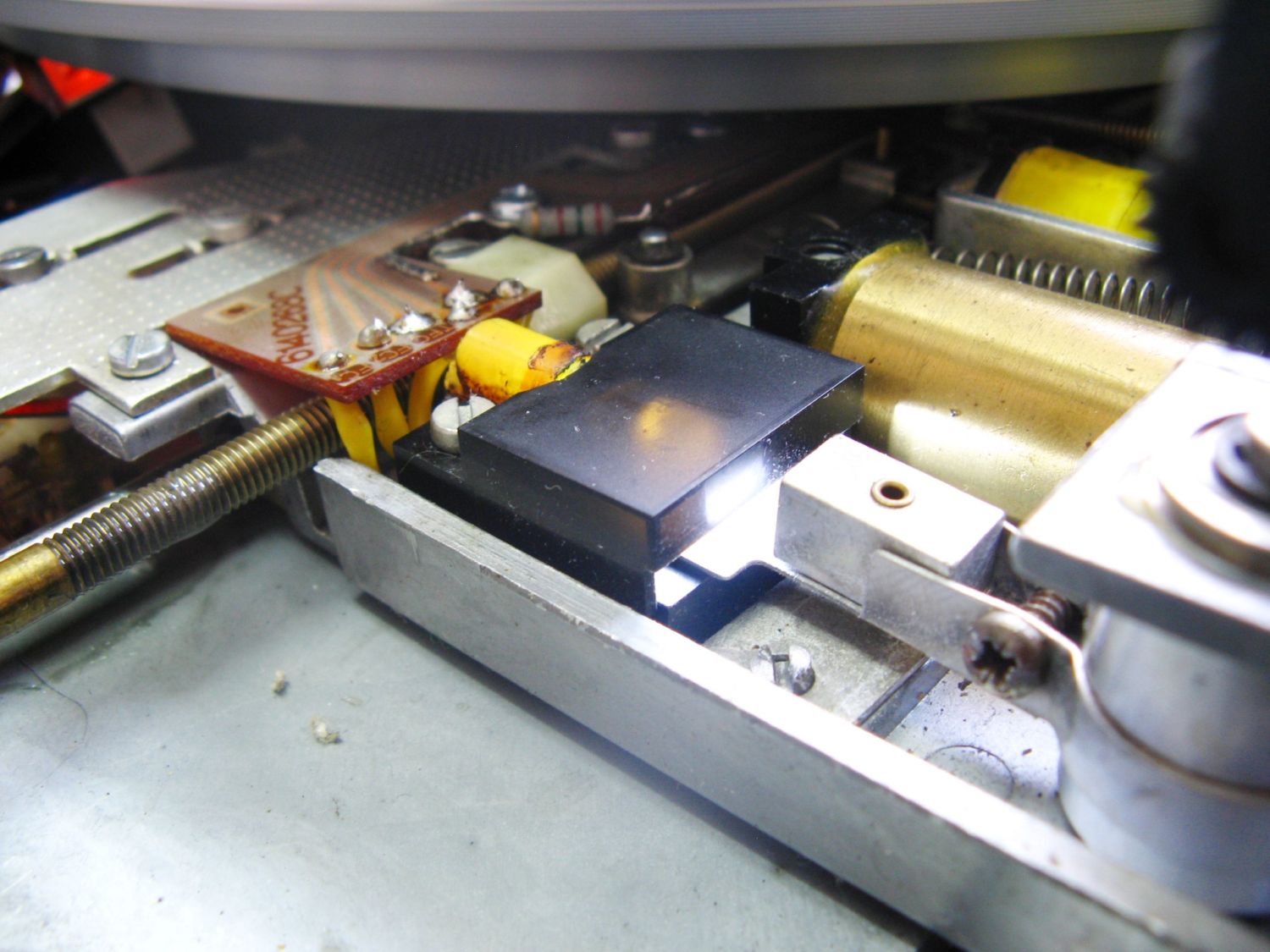
Learn from the mistakes of others - you'll not live long enough to make them all yourself!
|
|
-
-
Søren Hammer
- Joined on 01-07-2008
- Esbjerg/Denmark
- Posts 554
|
Re: BeoGram 4000 Restoration
That is so cool
I didn't knew that LED's has enough light intensity to work with a photo-transistor.
Beocenter 9300, Beogam CD50, Beocord 5500, Beomaster 3400, Beomaster 4400, 2 Beogram 4000, Beomaster 8000, 2 beogram 8002, Beovox S-75, Beovox MS150.2, Beovox RL6000, Beovox S-35, Beomaster 6000, 2 Beocord 9000, Beocord 8004, Beocord 5000, Form 1, 2x Beolink 1000, Beo4, MX3500, LS4500. Born 1993.
|
|
-
-
yachadm
- Joined on 06-24-2007
- Jerusalem, Israel
- Posts 687
|
Re: BeoGram 4000 Restoration
Soren, yes, it works, but you have to use a bright LED. As I mentioned before, between 15,000 - 50,000 mcd works well.
The next stages are now done.
As most of you know, I am not averse to using newer technology, especially where it can enhance the performance of the unit, but does not detract from either its reliability or "originalness". So, once again, I prefer to use LED's in the keyboard panel. Final pictures (and a short film) will show how good this unit looks with LED's, but for right now, here is the PCB.
This BG4000 (Serial # 215774 - a later production unit) has the 2 white lamps in Parallel, NOT in Series as is shown in the SM. So the choice of resistor applies to this parallel circuit only.
22V -> LED's -> 18.7V -> 470ohm 3W -> GND. That's the big resistor in the yellow area.
The "Warm White" LED's were sanded over to disperse the light more naturally.
The 2 red LED's are on independent circuits, but with a common 6.2V feed.
6.2V -> 220ohm 1/2W -> 2V -> split to 33 and 45 LED's.
Mounting was really simple - the resistors went directly into the locations of jumpers which were removed. 
Learn from the mistakes of others - you'll not live long enough to make them all yourself!
|
|
-
-
hemenex
- Joined on 04-23-2007
- Posts 375
|
Re: BeoGram 4000 Restoration
good gracious, FCH's from 1973
wasn't that DTL logic even obsolete when I started studying...
Seems we're pretty much the same age...
Had a look at your website - do you still remember CP/M ?
Gunther
|
|
-
-
-
tournedos
  - Joined on 12-08-2007
- Finland
- Posts 5,808
|
Re: BeoGram 4000 Restoration
hemenex:
good gracious, FCH's from 1973 ![Surprise]()
wasn't that DTL logic even obsolete when I started studying...
Well, B&O did get rid of DTL chips in later models...
...converting them literally into diode-transistor logic and analogue time
constants! The circuitry in 4002/04/6000 is madness 
|
|
-
-
yachadm
- Joined on 06-24-2007
- Jerusalem, Israel
- Posts 687
|
Re: BeoGram 4000 Restoration
Step1:
I would say the white led's give out far more forward light than the orginal underdriven incandescents did and if not carefully done this could cause problems in the 4000 more than the later models due to both photocells recieving light...
And that's exactly why I buff the LED's with sandpaper, to reduce the excessive forward intensity!
Anyway, LED's are all very nice, but nice looks are worth nothing if the machine doesn't work. I had a gut feeling that something wasn't right here, that I hadn't covered all the bases. Everything appeared to work right - I'll post more photo's later - but something was bothering me.
And with a classic unit like this, which someone threw away, I thought to myself, "Now, why would someone really want to throw this away?" What could have been so wrong with it? And then I thought - if it didn't sound right, that's a good reason for a layman consumer to get rid of his sound equipment.
Now in this unit, there is no preamp. It's (almost) a direct line from the stylus to the Din5 plug outside the TT. Well, except for the muting relay, which grounds the signal leads when the solenoid is not powered. I disengaged the muting contacts by inserting a toothpick between the flappers.
The 4 finger conductors on the tonearm (which protrude to fit into the MMC20 series cartridges) are R- Green; R+ Red; L+ White; L- Blue, looking from the front, Left to Right.
I traced them to the conductor block on the chassis, and I was getting a short on the L&R +ve leads, instead of on the 2 -ve leads. And L-ve was separate from R-ve, when they should have been common - Oh Boy!
Reversed wiring.
Now those of you who've worked on the tangential units and had signal problems know that this requires VERY MUCH patience, and slow steady work. It is incredibly time consuming, and sometimes frustrating.
I traced the crossed wiring to the small PCB inside the tonearm. Either the B&O assembler was asleep when this unit was made, or the tonearm was replaced at some time, and the technician was a complete idiot 
This is the tonearm conductor, with the correct signal configuration.

Learn from the mistakes of others - you'll not live long enough to make them all yourself!
|
|
-
-
yachadm
- Joined on 06-24-2007
- Jerusalem, Israel
- Posts 687
|
Re: BeoGram 4000 Restoration
This is the Tonearm PCB, with the +ve and -ve signal leads reverse-wired. Don't all rush now, but if your's looks like this, you've got some very patient work ahead of you. And if it turns out that more of you have this (I hope not), then there was a production defect. 
Learn from the mistakes of others - you'll not live long enough to make them all yourself!
|
|
-
-
yachadm
- Joined on 06-24-2007
- Jerusalem, Israel
- Posts 687
|
Re: BeoGram 4000 Restoration
This is the Tonearm PCB after redoing the wiring correctly. If your's looks like this, you're OK. 
Learn from the mistakes of others - you'll not live long enough to make them all yourself!
|
|
-
-
yachadm
- Joined on 06-24-2007
- Jerusalem, Israel
- Posts 687
|
Re: BeoGram 4000 Restoration
Well, this reverse wiring looks like an original production goof - apologies to the supposedly sleepy production assembler and idiot aftermarket technician!
In the BG4000 Service Manual Page 3-2 (and the SM's for the 4002 and 4004), the pickup schematic shows very clearly (and correctly) the order of the 4 finger connectors on the tonearm. The L&R +ve's are definitely the inner 2 fingers, and the L&R -ve's are definitely the outer 2 fingers. No doubt about that.
However, on Page 6-10, the PCB connections are shown with the reverse wiring configuration, according to the colors.
So, I can only conclude that one of the original design engineers got confused when he was committing his thoughts to paper. Apparently he wrote down the wrong connections, and that mistake was transmitted to the production line and of course to the Service Manual.
I'm not sure how reverse wiring would affect the sound, but for the point of technical excellence, if nothing else, any of you fellow perfectionists out there might want to correct this production defect.
And BTW, just to be certain that I wasn't hallucinating, I opened my BG4002, and disassembled the tonearm as I did in the BG4000, disabled the mute relay, and traced each of the 4 signal wires from finger connector to Din5 plug. I can confirm that the BG4002's tonearm is wired correctly from production. That confirmed that the BG4000's connections are defective.
Menahem
Learn from the mistakes of others - you'll not live long enough to make them all yourself!
|
|
-
-
Søren Mexico
- Joined on 09-13-2007
- Mexico city
- Posts 1,621
|
Re: BeoGram 4000 Restoration
yachadm: Well, this reverse wiring looks like an original production goof - apologies to the supposedly sleepy production assembler and idiot aftermarket technician!
For my BM 901 type 2602 I have 3 different drawings where also the spareparts numbers for the same transistors are different, this may depend on different suppliers, but the differenses in the drawings cost me a lot of work as I started out with the 2 manuals onsite and later found one more. So in the future I do as Eugene, nothing before I have checked the actual devise. I will come back with the whole story when I finish my 901.
Beosound 3000, BL 4000, BL 8000, BG 2404,BG 5000, BG CD50, Beocord 5000, BM 901, BM 2400, BM 4000, BV S45, BV 3702. There is nothing we cannot do, but a lot of things we don't want to do!!
|
|
-
-
yachadm
- Joined on 06-24-2007
- Jerusalem, Israel
- Posts 687
|
Re: BeoGram 4000 Restoration
Having now redone the main PCB with new caps, potis and some resistors, the 33rpm now regulates correctly - before it wandered all over the place.
2 remaining problems - perhaps I'm not doing something correctly.
Potis 1VR5 and 1VR6 adjust the DC Servo Motor voltage in < FF and > RW. I have my Fluke 187 RMS voltage meter connected, and I am getting a constant 10.6VDC in < and >, and adjusting the potis does not change that voltage.
The SM states to use a tube voltmeter, and adjust to bewteen 2.5V and 3.0V.
I don't have a tube voltmeter, I've used the DMM on my scope, but even that is showing 10VDC.
So, assuming that a DMM is fine, those 2 potis are not regulating.
A static check shows the associated transistors to be fine - what other checks should I look for to determine the fault?
Is it possible that 4IC1 is at fault - FCH131 - holy cow, where to find one? Normally those were very reliable, but one never knows.
Learn from the mistakes of others - you'll not live long enough to make them all yourself!
|
|
|
|
|