|
Untitled Page
ARCHIVED FORUM -- April 2007 to March 2012
READ ONLY FORUM
This is the first Archived Forum which was active between 17th April 2007 and
1st March February 2012
Latest post 05-21-2011 3:54 PM by Step1. 22 replies.
-
 05-05-2011 11:26 AM
|
|
-
 HarryPierce
  - Joined on 12-02-2010
- Posts 80

|
Hi Vintage Community,
I recently bought a Beogram 4004 (5525) on ebay. It arrived in decent condition on my doorstep. However, after plugging it in the following happened:
Pressing "start": The platter started spinning. The 33 light and the sensing arm light came on, but the slide did not move.
Pressing "33" Lights came on briefly then faded and one of the main fuses burned out. Slight smell of burning electronics became noticeable, but nothing fried itself visibly. 1IC1 seemed a bit warm after this exercise, but not overly so.
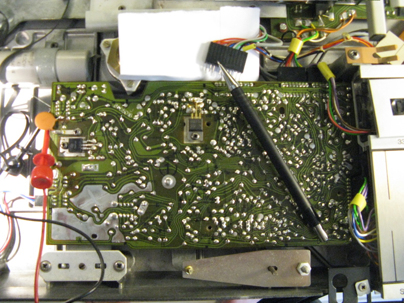
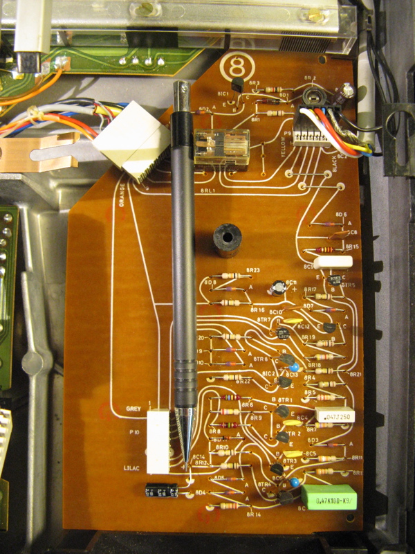
I extracted the main "1" circuit board to have a look. Here is what I found:
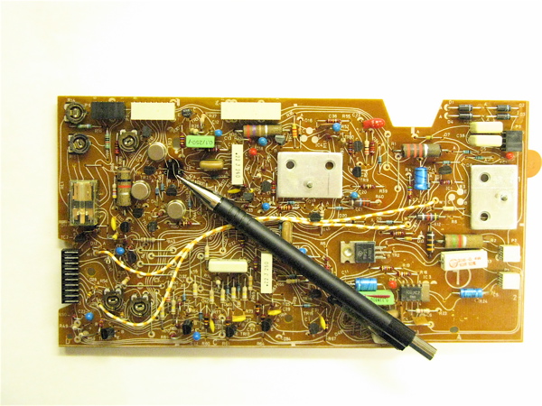
Visual inspection indicates that 1TR20 went missing (pen points to its location) leaving a black spot behind. I also noticed when I took it out that there was nothing connected to P2 (next to the connector to the table motor). The other components look 'normal' for this age, i.e. the potis look corroded, the larger resistors have a somewhat ragged look. Nothing looks burned out.
In absence of a circuit diagram I am a bit at a loss how to proceed with the repair. I did measure the voltages at 1IC1 and determined that it always puts out stable 21 V on its emitter as prescribed in the fault finding flow chart in the 4004 service manual fragment available on the internet. However, this does not depend on whether start is pressed or not. I unsoldered two of the legs of 1IC1 and determined that EC is not burned through, and shows rectifying behavior.
Any ideas and recommendations how to proceed would be greatly appreciated!
Thanks much in advance!
Rudy
|
|
-
-
yachadm
 
 - Joined on 06-24-2007
- Jerusalem, Israel
- Posts 687

|
Rudy
Incredibly difficult to start looking for the problem(s) by remote control, after the PCB has been savaged by someone else.
This is what it should look like after a correct restoration, and I can offer to do this for you.
Of course it is fully calibrated,and you can just connect it and start using it.
Menahem 
Learn from the mistakes of others - you'll not live long enough to make them all yourself!
|
|
-
-
HarryPierce
- Joined on 12-02-2010
- Posts 80
|
Thanks for your quick reply! Is there a way to confirm prior to repair that the items connected to the board are in proper order aiming to prevent killing the board again once it is fixed? Thanks!
Rudy
|
|
-
-
Step1
 
- Joined on 07-06-2008
- Manchester
- Posts 961

|
WOW, that is quite a failure! Can you find the rest of the can?
The H-bridge (the bit that drives the servo) does fail in these decks, I have seen this a few times and seems to be due to a partially siezed motor. In this case I would check there is not a short to ground at the output of tr20 (make sure plug 5 is connected!) either somewhere along the motor path, the motor itself (unlikely but not impossible) or any of the other transistors in the bridge. Also a miss-placed plug?
21v sounds healthy.
I think plug2 is for the led but can't remember to be sure...
It is normal for things to work in a momentory action when pressing the 33 key, as this was the record cleaning function.
If you join up you will have access to service manuals, although not sure how complete your copy is?
|
|
-
-
HarryPierce
- Joined on 12-02-2010
- Posts 80
|
Thanks for your insight!! Failure is not an option...;-). I read a bit up on motor controls to understand your H-bridge comment. I gleaned from the 4002 circuit diagrams that I have, that TR20 is connected to on of the leads to the slide motor ("servo"). A closer look at the circuit board revealed that the trace from emitter to P5 is indeed a bit 'browned'. The missing transistor and its blackened location complete the picture.
However, the motor is definitely not seized. The rotor spins lightly. It also does not seem to have a short circuit...it puts a nice sine/sawtooth curve out when I spin it by hand. Can I just apply <12V DC to the brown and orange leads that go from the npn bridge transistors to the servo PCB and see if it runs properly? Do these H-bridge transistors just occasionally fail? What I do not understand at this point is how the fuse blew out due to the missing TR20 when pressing "33". Doesn't this just disable the motor from going in one direction? There must be another problem superimposed...the missing transistor cannot cause a short, or am I missing something?
Plug 2/"LED": There is nothing inside the "can" that looks like a cable/plug or cutoff three-leads cable that was not connected...Which LED are you referring to?
Thanks!!
|
|
-
-
Dillen
  - Joined on 02-14-2007
- Copenhagen / Denmark
- Posts 5,008

|
It's not uncommon to see H-bridge faults happening for no obvious reason.
The carriage may have been blocked by something or one of the transistors had an internal scar.
It could, however, also be that the servo motor draws excess current because of internal debris from its brushes.
If one of the H-bridge transistors have failed, there's a good chance that one, two or even three others
have failed too because of the way, they are coupled. There's also a good chance that the previous repairer, who
removed one transistor, wasn't looking for more faults or simply didn't know much about it.
I suggest you replace all eight. I made a kit for this type of repairs a long time ago but I'm not sure if
it covers this version, I will have to check.
You can check the servo motor separately using an external DC source but if you apply an external DC to the H-bridge
it will have no control and won't work. Besides, if there are more shorted transistors, the board may suffer more damage.
And - Don't fit the platter motor plug to the wrong connector - the board and motor WILL suffer damage.
Most boards have a silk-screen printing near the connectors, telling the color of the nearest wire in the cable
that should be connected.
Martin
|
|
-
-
HarryPierce
- Joined on 12-02-2010
- Posts 80
|
Hi Martin,
Thanks for your input! With regard to "fit the platter motor plug to the wrong connector", is there anything that should be connected to that second plug (P2) labelled "LED"? I do not see anything in there that was disconnected and could fit there...
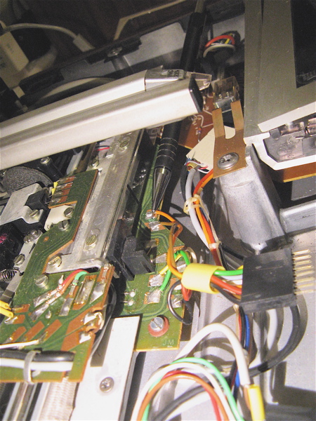
Checking the servo motor: I thought to connect a power supply where the orange and brown leads connect to the "slide motor board"-see location indicated by the pen in the pic below. These two leads would connect to the emitters of the H-bridge transistors if the board were in. Would that be o.k.?
What I am really wondering about is why the fuse blew after pressing "33"...I never laid sight on a 4000 series turntable before taking this one out of the box, i.e. I do not know if the slide would be activated when pressing "33", but I thought it would probably not, since it is meant for "wiping the record"? Is it possible that the slide is returned to its rest position after pressing 33 if it is in a position to the left before pressing 33? I did turn the threaded rod on which the slide moves a few turns to see if it is free to move before pressing 33, i.e. the slide may have been a few mm left of its rest position.
Thanks!
Rudy
|
|
-
-
Step1
- Joined on 07-06-2008
- Manchester
- Posts 961
|
 HarryPierce: HarryPierce:
Hi Martin,
Thanks for your input! With regard to "fit the platter motor plug to the wrong connector", is there anything that should be connected to that second plug (P2) labelled "LED"? I do not see anything in there that was disconnected and could fit there...
If there is no led present on the front left base of the record player then there is nothing to connect! I wouldn't worry about this plug at all.
HarryPierce:
Checking the servo motor I thought to connect a power supply where the orange and brown leads connect to the "slide motor board"-see location indicated by the pen in the pic below. These two leads would connect to the emitters of the H-bridge transistors if the board were in. Would that be o.k.?
Yes as long as the header remains unconnected you will get a good idea of the motor condition. Slowly raise the voltage from zero as these motors are very high quality and tend not to stall easily, should start turning at a very low voltage, although cannot tell you what that is right now!
HarryPierce:
What I am really wondering about is why the fuse blew after pressing "33"...I never laid sight on a 4000 series turntable before taking this one out of the box, i.e. I do not know if the slide would be activated when pressing "33", but I thought it would probably not, since it is meant for "wiping the record"? Is it possible that the slide is returned to its rest position after pressing 33 if it is in a position to the left before pressing 33? I did turn the threaded rod on which the slide moves a few turns to see if it is free to move before pressing 33, i.e. the slide may have been a few mm left of its rest position.
If the slide is out and the Beogram is then plugged in, the platter will start spinning regardless and the beogram will be out of standby and wait for your next command, i.e. drop arm, off or whatever - it will nothing! pressing 33 at this point will also have no effect unless the platter is rotating at 45.
You will have to investigate why the fuse failed, make sure all the plugs are correct as Martin suggested above. If you have a powersupply with ammeter then why not disconnect the beogram transformer and slowly raise the input voltage whilst watching current drawn..
Just one more thing - at the very least, put the cover over your cartridge it would be a shame to accidently damage it when you are close to testing the player!
|
|
-
-
HarryPierce
- Joined on 12-02-2010
- Posts 80
|
Thanks much for your detailed input!! Much appreciated! I will test the motor and do the powersupply ramp-up you proposed and report back!
With regard to the cartridge, I do not have a cover at this point (a typical ebay trade, I guess...). There is also a dent in the aluminum top of the cartridge (the 33/45 speed adjust panel popped out during shipping and may have hit the cartridge, i.e. I will probably have to look for another one...live and learn...;-).
Rudy
|
|
-
-
HarryPierce
- Joined on 12-02-2010
- Posts 80
|
Thanks again for all your input! I had a bit of time and tested the slide motor. It seems to run well and the slide moves reasonably fast at about 4.5V while drawing about 60mA. That much for "why the H-bridge transistor died"....
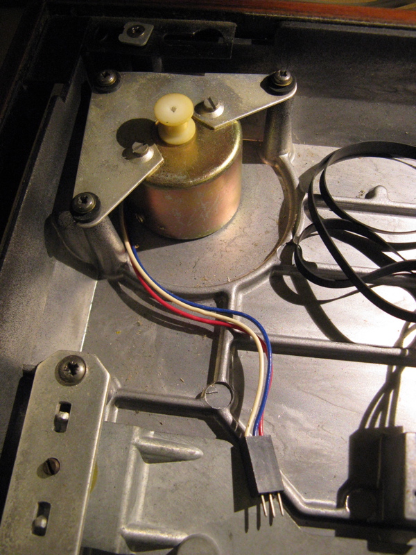
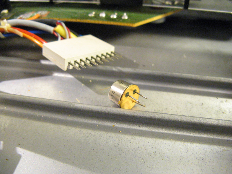
I am a bit confused about testing the motor for the table. I think I have the "servo controlled DC motor" (see pic below). I was wondering how one can bench test such a motor? Any advice would be greatly appreciated! Are the three leads for supply voltage and control signal? Which of the red/blue/white leads is for what? Thanks!
Rudy
|
|
-
-
HarryPierce
- Joined on 12-02-2010
- Posts 80
|
That was quick! I received some very friendly (off line) advice, and ran the motor on its motor leads (red and blue), and at 4.5 V it draws 30 mA. It spins up nicely, but makes a bit of a ruckus, like it may need a bit of lubrication. Although with platter mounted I was not able to hear anything before the fuse blew. Is this noise normal when it runs w/o load, or do I need to take it apart? Thanks!
Rudy
|
|
-
-
HarryPierce
- Joined on 12-02-2010
- Posts 80
|
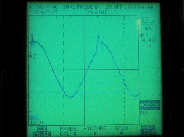
O.k...last post before bed time! I ran the motor for some time while playing with the oscilloscope. The motor quieted down considerably and now is virtually silent. The current went down to ~15 mV at 4.4V. I guess some old lubricant...I hooked up the oscilloscope to the generator output (blue/white) and it shows 200mV peak to peak (see pic below). Question: Is it normal to have such spikes in the curves? Thanks!
Rudy
|
|
-
-
-
HarryPierce
- Joined on 12-02-2010
- Posts 80
|
Hi Olly,
Thanks for your advice! Much appreciated! I think, I need to first check the H-bridge transistors and add the missing TR20 before I can start consistently measuring the board outputs etc...When I played with the motor yesterday, I tried many times to start/stop it to see if it would get stuck sometimes and draw a high enough current to blow the 250mA fuse, but it did not. But then, at the beginning I had that "bearing noise", and it seemed to run rough initially, and there was the belt putting tension on the bearings... So, there may have been a temporary "seizure" at the moment when I blew the fuse when pressing "33".
If the motor seizes, does that typically damage the 8-pin IC that controls it? Do you know what IC that is? The cryptic labeling does not seem to lead anywhere in terms of replacement possibilities etc...
Thanks!
Rudy
|
|
-
-
Step1
- Joined on 07-06-2008
- Manchester
- Posts 961
|
Just in case you have not realised please bear in mind that the 250mA rating is on the mains side which would equate to about 60W @ 240V on the primary before failure so this will mean it will take a couple of amps on the secondary side before the fuse fails! I think the solonoid draws a couple of ampsinitially but the circuit is designed to reduce current to a much lower holding level within a few milliseconds so should not pose a threat to the fuse.
Anyway, looking to measure a 'fault current' of 250mA is only going to lead you down the wrong path. I suspect you will be looking for a near dead short. Get what you know is broken right first and work from there! One bit at a time!
Maybe check some of the transistors? Also have you unplugged the transformer and tested alone although this does not sound the case I have had a duff unit which is still awaiting a donor!
Keep up the good work though!
|
|
-
-
HarryPierce
- Joined on 12-02-2010
- Posts 80
|
Ah yes!! I now remember transformers from my Physics classes...;-). I agree this must have been a full short somewhere. Maybe something mechanical in the key pad? It happened when I pressed down the 33 button...I cannot imagine it is the transformer, since I did not touch it when it happened. Also: after that event, I put in a new fuse, and I got the prescribed 21 V after the supply transistor, and the fuse stayed happy.
Rudy
|
|
-
-
tournedos
 - Joined on 12-08-2007
- Finland
- Posts 5,808
|
HarryPierce: If the motor seizes, does that typically damage the 8-pin IC that controls it? Do you know what IC that is? The cryptic labeling does not seem to lead anywhere in terms of replacement possibilities etc...
I believe it is exactly as it says on the top - a C1003 (or µPC1003) by NEC and looong discontinued. It was used a lot in the 1970's in various cassette decks etc.
Seems pretty robust though, I don't think I've seen any discussion about it failing.
|
|
-
-
HarryPierce
- Joined on 12-02-2010
- Posts 80
|
Hi There,
Thank you very much for all your great input!! I spent some more time with my 4004 baby, and made some progress (perhaps). First, I heeded Olly's advice and hooked the board up to my power supply. It turned out that the high current only occurs when P4 is connected (pen points to it in the picture-I apologize for the poor focus-forgot to turn on macro). When I disconnected it, I was able to run the motor when pressing 33 (~0.13 Amps at 25 V DC at P3-1) and the 33 light comes on under the rpm adjuster wheel. -text continues after the picture-
When connecting the plug, a high current occurred (~0.5 Amp/<2 V). I took the board under the key pad out (labelled "8") to check the components. What I found under the P8 on that board was the missing BC144 transistor (see pic). The previous owner-joker probably thought to better send me all the parts...;-). I decided to keep the NTE128 replacement in the H-bridge despite the fact that the found BC144 seems to be in working condition. I should point out that I also replaced all elcos on the main board, made sure that all potis actually work, and checked all semiconductor components with the component check function of my lovely new (old) Fluke 97, i.e. I think the board may be in working condition-text continues after pic-
This may well have caused a short on the plug since the solder points probably contacted the transistor housing. When examining the voltages on P4 on the main board when pressing "33" before taking board 8 out, it seemed that only pins 2,3 and 7 pulled up to significant voltages (24,24,5.9V). When checking the corresponding pins on the plug against ground, I found that 3 had a short to ground.
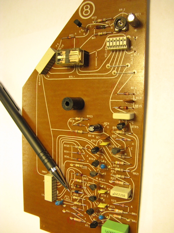
At that point I decided to check all diodes and transistors on board 8 and exchange the two elcos (see pic below). I found that 8D11 was burned through. Since I did not have the exact 1N4148 replacement, I scavenged a 1N4002 from some discarded board I had lying around. The data sheet seemed to suggest that the 1N4002 can take more than the 1N4148, but I am not sure if this is a good idea with regard to frequency response and all that-any input here would be appreciated. I will order the proper one with my next Newark shipment...-text continues after pic-
After putting the board back in and making all connections the short at pin 3 of P4 was gone (1.9MOhm now), I ramped the voltage on the main board back up to 25 V, and experimented with pressing "33" under slowly relaxing current limit. Unfortunately, the current is still fairly high. I went up to about .8 Amp, and reached a voltage of about 5.7V. At that point I got a bit nervous and decided to write this post hoping for some expert advice! ("A man's gotta know his limitations"-Clint Eastwood/Dirty Harry...;-).
It would be quite interesting to know what the current is in a properly working deck when pressing "33".
One more question remains: the 8R2 trimmer on board 8 was set all the way to zero Ohm when I took it out. That seemed strange, but after finding the BC144 I think nothing can be taken for granted in there...Any advice to adjust R2 would be appreciated.
Thanks much in advance!
Rudy
|
|
-
-
tournedos
- Joined on 12-08-2007
- Finland
- Posts 5,808
|
The possibly problematic part of your board 8 contains only the Datalink control circuitry for the deck. So, it might be possible to isolate it from the rest for testing (disconnect the four traces coming down from above the black plastic tower in your pic, and leave P10 disconnected).
The upper part with the relay is the muting circuit common to all these (two-channel) decks. R2 adjusts its delay and is in no way critical. Middle position would sound nicer than all the way to one end, though.
The service manual snippet containing 4004 specific stuff we have on site is next to illegible, so I'm not sure what the function of that diode is. 1N400x might work in place of a 1N4148 depending on application, but it is designed for rectification and will be worse in just about every other spec compared to a small signal diode. Order 50 pcs while you're at it, they cost next to nothing 
Unfortunately I can't guess on the correct startup current, but it won't be too small as the motor starts up. Also, some circuits might not work properly when the supply voltage is too low.
EDIT: just realized there's a better scan in another service manual. D11 seems to be inline the supply to part of the control circuitry. If it had burned short circuit, there might be a problem around TR1-2-3-4.
Also, leaving P10 disconnected will disable some functions. The "33" start should still work.
|
|
-
-
HarryPierce
- Joined on 12-02-2010
- Posts 80
|
Hi Mika,
Thanks much for your input! A possibly naive question: How do I disconnect the four traces? I can see how to do the two right ones by taking the jumpers out, but the ones on the left?
I do not think that I have shorts anymore...the three "serious voltage" carrying pins on P4 of the main board seem to lead now into "reasonable resistances". Can I assume based on the 250mA fuses that a current of about 120V/25V*0.25A=1.2A will be o.k. and not kill additional stuff? (well, actually, I guess I answered this question already by burning the fuse...aeverything that could get killed under such conditions probably did get killed...;-)
Thanks!
Rudy
|
|
-
-
tournedos
- Joined on 12-08-2007
- Finland
- Posts 5,808
|
You would need to cut the traces on the circuit board and later
bridge them back. It was just an idea and maybe not worth the trouble,
perhaps it would be more useful to just check the resistances on the
supply lines of this board (P8 pin 9 = 30V, P8 pin 8 = 21V). If they
don't seem much of a load, I can't see how plugging the board back in
would harm anything.
The calculation on the mains side fuse will only give a rough upper limit to the constant current you can draw. You should rather think of the power consumption. Earlier you said you gave up at 0.8A @
5.7V - that would be only 0.8*5.7 ~= 4.5W, which I think is still way
less than the deck will need in full operation (I would guess closer to
20W, i.e almost one amp at the nominal supply voltages).
|
|
-
-
HarryPierce
- Joined on 12-02-2010
- Posts 80
|
Allright!! Life signs! I obtained a set of jump cords and jumped plug P4 (see pic below-what a beautiful mess...;-). Then I hooked my multimeter sequentially into each of the connection and measured the current, while operating the power supply under 0.5 Amp current limit. This quickly allowed me to identify pin #3 as the offending current sink.
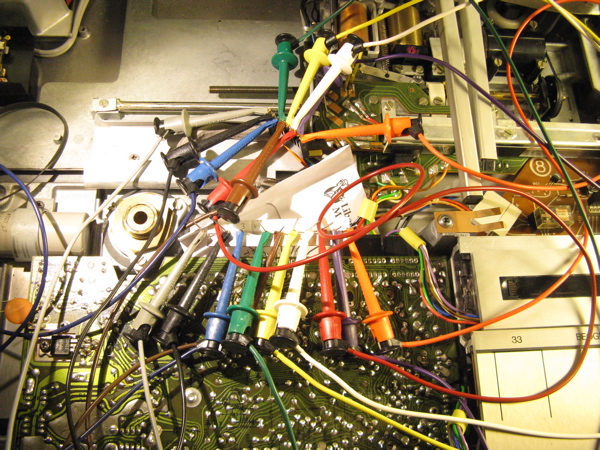
The orange lead on pin #3 connects to board "8" and interacts with both the data link and the mute circuits. I first suspected the mute circuit to be bad, and removed the relay and 8IC1. This did not reduce the current, so I soldered them back in. On to the data link circuit. Here the burnt out 1N4148 diode gave me the clue to check 8C11 which connects to ground. Indeed it turned out that this capacitor had a short circuit. I replaced it with a 2.2uF elco (see pen tip in pic below) and also exchanged the temporarily inserted 1N4002 with a proper new 1N4148. Then I put
everything back together and fired it up, still using the regulated power supply. Voila-no more short circuit. Pressing "33" now draws a smooth 0.19Amp at 25V DC. The other functions also came to life. Pressing start launches the slide towards the table searching for a record. Stop sends it back etc...
Unfortunately, a new problem made itself apparent (see my next entry "BM 4004 Solenoid Problem?")
|
|
-
Page 1 of 1 (23 items)
|
|
|