|
Untitled Page
ARCHIVED FORUM -- April 2007 to March 2012
READ ONLY FORUM
This is the first Archived Forum which was active between 17th April 2007 and
1st March February 2012
Latest post 11-04-2011 10:21 PM by Andre. 51 replies.
-
 05-03-2011 3:31 PM
|
|
-
 Andre
Andre
 - Joined on 12-04-2010
- Cape Town
- Posts 56

|
Beogram 4002 Series 5511 Restoration/Repairs
Hello Gentlemen
I am a longstanding Beogram owner going back 30+ years. My Beogram 1000 was the first 'decent' turntable I owned and I still remember how I swallowed and gulped at the purchase price when I needed to purchase a new SP14 cartridge for it around year 1976. During the following years, I purchased two 1900 turntables, as well as two series 4000 which were in total disrepair and beyond resque or so the seller said.
A few years later, I bought a 4002 series 5511 which is in superb condition cosmetically and I briefly used it a few times but I always had issues with the platter speed and various other functions.
A few weeks ago and after years of having it in this non-functioning condition, I decided to troubleshoot the problems although I know virtually nothing about electronics.
The first fault was easy to spot. The arm leadscrew pulley was cracked in half. I repaired the problem by using a pulley from one of my 4000's, centre-drilled it in my lathe to make it fit on the thinner leadscrew shaft of the 4002.
Next up, I attended to the non-functioning 3V dc motor and traced its problem to an open coil on the rotor. I carefully fished-out the joint on the rotor's underside, cleaned it and re-flowed fresh solder on the joint which restored the faulty coil. I also re-soldered one of the varistors around the coils as the joint had also desoldered.
The motor brushes were almost completely gone as these had arc'ed, making them unserviceable. I then managed to make new brushes for it, cleaned the commutator segments and reassembled the motor with a fresh drop of Elna sewing machine oil at each shaft end.
I tested it out of the deck with a powersupply set at 3.4V and the motor spun perfectly and silently.
My last repair took almost an entire day's worth of testing and cleaning the control panel switch contacts and testing them repeatedly with my multimeter set to "continuity" to ensure all controls were now reliable.
By this time, almost a week over the Easter holidays had elapsed after continuous work on the 4002. I was dead-tired and should have stopped there but I thought "Victory is within reach".
And this was where it all went wrong. I once more tested all controls and functions with the mains plugged in. All controls worked, the motor spun the platter instantly to speed, the carriage worked and so on.
I went to fetch a record, a strobe disc and its cartridge. One minute later when I returned, I found a smoking motor and the top left corner of its pcb where the 4 diodes are located, also severely burned.
For some incredibly stupid reason, I didn't look properly where I plugged the motor into the board. It went into socket P2 instead of P1 and the motor got far too many volts.
So, back to square one. It took many, many hours to clean the burned wires and remove the fried varistors from the motor. And the newly replaced brushes.
I found replacement coil wire - almost identical - and re-insulated the rotor, preparing for a motor rewind. Fortunately, I had measured the coils' dc resistance before and counted the number of windings when I removed the old wire.
So, I rewound the motor. The original measured resistance for each coil with the wires removed from the commutator tags was 23 ohms and the new windings measure 25 ohms. In the pic, you can see what I did to replace the now fried varistors. I used 1 diode and 1 zener between each commutator segment.
The motors spins instantly and quietly but I haven't yet tested if the speed is right.
My apologies to all about this very long post.
Also found was a real mess on board 8, under the control pad. It looks as if the previous owner had a mono switch installed, bridging the + of the left and right channels.
Another mistake on my part. Before cutting away the non-standard tone arm wires at the 6-pin connector, I should have taken photographs of the correct sequence and colours of the wires going into this connector.
The circuit to this connector underneath the board is untouched. I have removed the non-standard armwire and I want to rewire the male plug going into the 6-pin socket but my measurements from the other multipin connector to the left, doesn't make any sense.
Tracing the wires from there, it looks like the earth return wires of the L&R armwires had been commoned. All I now is that the wire from pin 6 must be earth, going to the earth tag at right back of the 4002.
Even though all connections or circuit traces between the two multipin connectors are original, I measure continuity between some of these pins on both connectors , which I don't understand at all.
So, now I have only a single "certainty" for re-wiring the 6-pin male connector: Pin 6 (extreme right) is earth which goes to the earth tag at the rear of the turntable, leaving 4 more wires to account for in their correct positions - Left channel earth return (blue), Left Channel (white) +, Right channel earth return (green) and Right Channel + (red).
If the earth return wires of the two channels are commoned as it appears at the connector to the left of my pic, I have even more troubkles to understand this wiring as all this leaves two extra connector pins free and unaccounted for?
i have in the meantime cleaned and repaired the board at top left, as well as replacing all four burned diodes with new items. All functions work again, including the motor.
I measured the voltage at socket P1 on the board and its output measured 3.4V initially. Later on, I measured just below 8V there, which indicates a fault. Nothing is smoking but the large soldered surface near socket P1 feels too warm for my liking so something here is also not right.
Please, can any member here come to my assistance to get this turntable working properly again - especially with the correct wiring of that 6-pin connector on board 8.
Any replies or assistance with these problems will be much appreciated. I have jpegs of the problem areas but don't know how to upload them.
Regards
dauphine
|
|
-
-
Søren Mexico
 
- Joined on 09-13-2007
- Mexico city
- Posts 1,621

|
Re: Beogram 4002 Series 5511 Restoration/Repairs
Thats a superb job you have done there, and help wil certainly arrive from the experts. Here is how to upload Images.
First go to your account, upper right corner, click signed in as, scroll down click "my files", down left you have browse and add file, on the right add folder, if you want to create diff. folders, enter folder name and click "add folder", open folder, now click "browse", in your computer find the pic you want to upload, click "open". Now click "add file", your pick will upload and show in the folder, next pic same.
to post a pic, open your new thread or reply to one, text your answer or opening remarks, click the film strip in the menu, click "browse",
Your files will show, click the folder with the pick, double click the pick, the pick will show where your curser was placed before you clicked the film strip.
Before uploading, edit your pics down to some 640 x 480 pixels, that will give you a faster upload and the pic will fit to a forum page.
Below a bad pic from my uploaded files

Beosound 3000, BL 4000, BL 8000, BG 2404,BG 5000, BG CD50, Beocord 5000, BM 901, BM 2400, BM 4000, BV S45, BV 3702. There is nothing we cannot do, but a lot of things we don't want to do!!
|
|
-
-
Andre
- Joined on 12-04-2010
- Cape Town
- Posts 56
|
Re: Beogram 4002 Series 5511 Restoration/Repairs
 Hi Soren Hi Soren
Thanks for the instruction on how to post pics. I have uploaded 4 images, one of which shows where I currently have a problem with wiring. Two others show the rewound motor coils and new brushes (profiled afterwards to fit the radius of the commutator tags) and the last pic shows the 4002 before work started.
Tomorrow, I will upload two more images of the pcb where it heats up far too much when 220V ac is plugged in to the turntable. Also, the P1 socket on the board for the 3V dc motor now puts out almost 8V dc after measuring an initial 3.4V dc immediately after I replaced 4 damaged diodes at the top left of the board.
I have found a way to remove the pins from the male 6-pin plug without damage and solder in the new arm lead to the amp if someone can please provide guidance as to which wire goes where.
Apologies for being unable to add the slash across the "o' if your name.
Regards
dauphine  
|
|
-
-
Eugene
  - Joined on 12-17-2008
- Posts 589
|
Re: Beogram 4002 Series 5511 Restoration/Repairs
Nice work on the coils. Do you have the service maunal or at the very least the electrical diagram for your Beogram. That would ber helpful.
The only other recomendation I would make would be to replace the remainder of the original electrolytic capacitors still in the deck.
|
|
-
-
Søren Mexico
- Joined on 09-13-2007
- Mexico city
- Posts 1,621
|
Re: Beogram 4002 Series 5511 Restoration/Repairs
 dauphine: dauphine:Apologies for being unable to add the slash across the "o' if your name.
The only one, on the forum, using the correct Ø in my name is Mika from Finland, and he only use it to make fun of me  . .
Beautiful pics. After the mains there is usually a power bridge, I would start there checking the V after the bridge and trimmers thereafter, but as Eugene says, you will need the drawings and the service manual, where you will find the correct values and how to's, to addjust everything, new electrolytic caps is also needed in a deck of this age.
Also try the search function on the forum, a lot of 4002s has been repaired before.
To get the manuals on site you will have to sign up for a Silver or Gold membership, if you have more Beo equipment, thats a good deal.
I have repaired and rebuild BG 2404, BG 5000 and BG 6500, but never a BG 4002, now cool down for a day or 2, there will be more answers from members that knows a lot more than me within the next days.
Regards from sunny Mexico
Beosound 3000, BL 4000, BL 8000, BG 2404,BG 5000, BG CD50, Beocord 5000, BM 901, BM 2400, BM 4000, BV S45, BV 3702. There is nothing we cannot do, but a lot of things we don't want to do!!
|
|
-
-
Søren Mexico
- Joined on 09-13-2007
- Mexico city
- Posts 1,621
|
Re: Beogram 4002 Series 5511 Restoration/Repairs
Searching I found this one it may help you, anyway its interesting, made from our member Yachadm
Beosound 3000, BL 4000, BL 8000, BG 2404,BG 5000, BG CD50, Beocord 5000, BM 901, BM 2400, BM 4000, BV S45, BV 3702. There is nothing we cannot do, but a lot of things we don't want to do!!
|
|
-
-
tournedos
  - Joined on 12-08-2007
- Finland
- Posts 5,808
|
Re: Beogram 4002 Series 5511 Restoration/Repairs
Søren Mexico: The only one, on the forum, using the
correct Ø in my name is Mika from Finland, and he only use it to make
fun of me .
Apart from the Danes of course, who have it directly on their keyboard - I use copy & paste
@dauphine, that's some determination with that motor!
To get you a little bit further, the wiring of the P9 connector on board #8 is as follows:
- L out
- n/c
- R out
- n/c
- signal ground
- shield ground (sleeve of the cable / DIN connector)
Dunno which the way numbering goes in your pic, but you should be easily able to work out which is pin 6.
EDIT: Duh, pins 1 & 6 are clearly marked on the PCB!
|
|
-
-
Andre
- Joined on 12-04-2010
- Cape Town
- Posts 56
|
Re: Beogram 4002 Series 5511 Restoration/Repairs
   Hello All (Soren Mexico, Eugene, Ben A and tournedos) Hello All (Soren Mexico, Eugene, Ben A and tournedos)
I am overwhelmed by your replies, advice and goodwill. Thank you ad infinitum and good health and Peace to you all.
There may well be further issues but I am sure I will overcome them all. As much as I would like to continue immediately with repairs, I have to stop for a day to cleanup my workbench as it bears all the signs of frenzied activity, especially with efforts to find suitable wire to rewind the motor coils - finally liberated from an old relay from one of my cars.
So, IF the motor runs to the correct speed without interference with the audio signal, I will be very pleased to share my repair details with anyone here, should there be anyone here with a dead motor problem.
As mentioned, the following problems remain: The overheating board (pics with pencil indicates where), the increased vdc output on socket P1 (up from 3.4V to almost 8V) and then the correct wiring of the P9 connector.
@ soren
Apologies for the stupid question. In my mind, I numbered 1 to 6 from left to right, which I think corresponds with your post. To confirm how I understand your explanation, pin 1 extreme left on the connector is Left channel + (White). Pin 2 is N/C - what does N/C mean? What colour code? Pin 3 is R out Left channel + (Red), Pin 4 again N/C?, Pin 5 signal ground. By this I understand commoned (twisted together) ground/shield wires? and lastly Pin 6 shield ground (sleeve of the cable/din connector). This is a problem - I have plenty of original grey din type cable here from which to reproduce the original wiring.
However, I replaced this cable years ago with a 'modern' good quality phono lead, going to a pair of phono jacks at the rear of the 4002.
This cable has Right channel + (red) and its earth return. Left channel + (white) and its earth return. Between them, runs a 5th wire which is usually connected to the earth tag of my amplifiers or pre-amps I have in use. It was this (5th earth wire) I soldered to pin 6 and to the 4002's earth tag at the rear of the turnable. Hope I got this right? Don't know what N/C means and I don't know if the earth return wires from both the left and right channels should be twisted together and soldered to pin 5, signal ground.
Once more, apologies for these stupid questions but B&O's way of doing things is certainly different to my other turntables.
Regards
dauphine
Apologies again. I pic of the pcb has been uploaded twice and I don't know how to delete 
|
|
-
-
tournedos
- Joined on 12-08-2007
- Finland
- Posts 5,808
|
Re: Beogram 4002 Series 5511 Restoration/Repairs
dauphine: This cable has Right channel + (red) and its
earth return. Left channel + (white) and its earth return. Between them,
runs a 5th wire which is usually connected to the earth tag of my
amplifiers or pre-amps I have in use. It was this (5th earth wire) I
soldered to pin 6 and to the 4002's earth tag at the rear of the
turnable. Hope I got this right? Don't know what N/C means and I don't
know if the earth return wires from both the left and right channels
should be twisted together and soldered to pin 5, signal ground.
n/c
= not connected, those two pins go nowhere on a 2-channel 4002/4004.
The original DIN cable has only one signal ground connection, so your
RCA cable will need to share it for both channels. The shield ground
(sleeve in DIN) will have to go to the shield earth on the amp. I think
you have everything correctly here.
***
The IC3 your pencil is pointing at doesn't look fried to me - the metal tends to go black like that simply due to old age (some chemical reaction I think).
Test point voltages at P3 are specified like this with the motor connected and turntable running:
- pin 3: 8.5 V
- pin 2: 5.5 V
- (pin 1 is the tachometer return signal)
...which would give about 3 volts between pins 2 & 3, but you should not measure it like that, measure against the ground.
Pin 3 is a "rigid" voltage output, and the motor controller IC drives
pin 2 to keep the required speed. It might well drop near 0 without a
motor, giving you now ~8 volts between 2+3 with no motor connected.
P2
is the connector for the power LED - certainly not where you should
plug the motor, but the lucky thing is that doing that is not going to
damage the motor control circuitry driving P3!
So... there's a
good chance that everything is fine and you could just plug the motor
in, but wait at least for a second opinion before doing that!
|
|
-
-
Andre
- Joined on 12-04-2010
- Cape Town
- Posts 56
|
Re: Beogram 4002 Series 5511 Restoration/Repairs
Hi Guys
Hope you are having a good weekend. With the kind assistance of the members here, I have re-wired that phono out 6-pin connector on board # 8. I decided to discard the fancy bit of cable I wanted to use as it was too unwieldy so I found a piece of old school phono cable with additional screen and the pic shows how I did the job.
Just about before the clock struck midnight, I refitted the main board, plugged in all the connectors, fitted the sub-platter, the belt and the platter, the cartridge and a record. And of course double-checked that all connectors were correctly orientated and the motor plugged in at P1.
Connected to the mains, the platter rotated...only through 90 degrees.
You may recall I mentioned that one large soldered area of the board got a bit warm, so a friend suggested I raise one large resistor 1mm above the board, which I did. So there's no more problem in that area. (I spoke too soon, see the following post ) )
Continuing investigation why the motor doesn't spin, I re-checked the soldering on that resistor but all was fine.
Next, I disconnected the 3V dc motor and connected it @ 3.4V to my power supply and it spun perfectly as it did on and off the board.
This morning, I did some measuring but I admit I'm out of my depth as I don't know how to interpret the readings I got.
AT THE POWER IN SOCKET, SOLDER POINTS MARKED IN RED - A,B,C,D.
So, from A to the top check point I measured 12.96V
B) to top checkpoint, 13.40V
C) to top checkpoint 0V
D) to top checkpoint 31,6V
Same socket, 2nd checkpoint
A) 12.9V
B)13.35V
C)31.5V
D)0V
MOTOR SOCKET (Marked 1,2 and 3) Top checkpoint
1)0V
2)0V
3)0V
Second checkpoint
1)0V
2)0V
3)0V
If the same check is done (on 1,2 and 3) but this time touching on the either of the large soldered areas - 1, 2 and 3 each shows 8.65V
What do you make of this? Does this mean there's no power at P1?
Everything else still works. Does the work I did on board # 8 have any bearing on this? Could it be that the large capacitor 4700uf 63V has failed?
Any replies or advice much appreciated as always.
dauphine

|
|
-
-
Andre
- Joined on 12-04-2010
- Cape Town
- Posts 56
|
Re: Beogram 4002 Series 5511 Restoration/Repairs
It plays - Atrociously!
Now the long road to full recovery starts. I'm under no illusions that what still has to be done is minor. Earlier, just after my previous post, I was going to remove the board once more for close inspection incase I could see or measure anything obvious. On the spur of the moment, I decided to try once more as I was interested to find out if both channels work after the work on board 8 yesterday.
So, I plugged it into an amp and wanted to brush the stylus but instead, put a record on, pressed "Start" and 33 and still nothing. I repeated starting it and pressed 45, and it rotated, the arm dropped gently and I heard sound from both speakers - no hum, nothing
I noticed the belt was not riding dead centre on the pulley crown so I raised and re-glued it. The arm has not been set up - only a provisional 1.3g dialled in. It also is not parallel with the detector arm as there's a bit of toe-in visible in the pic.
That spot on the PCB still gets a little warmer than I like so this will have to be checked.
It only spins when 45rpm is pressed. And the speed is slow and a few times the platter needs to get a little push to get started.
In the pic you can also see the IEC mains socket I fitted, as well as some new phono jacks as I dislike trailing cords.
So, the word is methodically, I will go through every single bit needing attention as far as my limited electromechanical skills allow. The sound I heard tonight, holds great promise.
A fine weekend to you all.
dauphine
|
|
-
-
Eugene
- Joined on 12-17-2008
- Posts 589
|
Re: Beogram 4002 Series 5511 Restoration/Repairs
I would replace all the electrolytic capacitors. As shown in your photos you have 3 in the vicinity of your overheating issue, one a 4,7uf us in circuit with the small IC you are pointing to with your pencil.
It may not solve your problem but considering the age of the set 30+ years those caps are probably pretty much dried and spent by now.
|
|
-
-
Dillen
 - Joined on 02-14-2007
- Copenhagen / Denmark
- Posts 5,008

|
Re: Beogram 4002 Series 5511 Restoration/Repairs
Nice work so far !
"I noticed the belt was not riding dead centre on the pulley crown so I raised it"
Did you try with the platter mounted ?
Martin
|
|
-
-
Andre
- Joined on 12-04-2010
- Cape Town
- Posts 56
|
Re: Beogram 4002 Series 5511 Restoration/Repairs
Hi Martin
@ Eugene
Thanks so much for the interest and advice from beoworld.org. Yes, The belt was fitted together with the platters. Initially, I noticed the belt was riding against the motor pulley's top flange and the belt was scrubbing a little on the top platter's underside. Raising the motor pulley fixed the problem.
Today, I will do some more work to see if I can get the arm to track across the entire record
Regards
dauphine/andre
|
|
-
-
Dillen
- Joined on 02-14-2007
- Copenhagen / Denmark
- Posts 5,008
|
Re: Beogram 4002 Series 5511 Restoration/Repairs
If the subchassis is riding high, it may be because the three leaf springs were badly adjusted (too tight).
The subchassis should be able to swing freely a couple of millimeters in all directions, also up and down,
with the belt and platter mounted and a record on.
If it's held against the top by the leaf springs, the damping and isolation of the subchassis will not work
and the belt will ride too high on the motor pulley.
In severe cases (in some versions), it may even block the carriage movement so worth
checking in your case, I think.
Martin
|
|
-
-
Andre
- Joined on 12-04-2010
- Cape Town
- Posts 56
|
Re: Beogram 4002 Series 5511 Restoration/Repairs
Greetings, Martin
Thanks once more for the valuable advice. As it was a beautiful day here in Cape Town, I reluctantly took a few hours away from the 4002 but started again an hour ago. As I go along the path of rehabilitation, I will post some news regarding progress. I have 4 other turntables in use - mostly Garrard 301's, a Micro MR-711 direct drive and a Micro Seiki BL-51 - all hooked-up to their individual amps and pre's but I have another amplifier waiting for the 4002 when this is finished.
Everything will stay for now with the cover plates off to allow easy access for work in progress. I have just now made what I think is a small improvement for dis-assembly. I changed the slotted screws below holding the casting for the cover for the same size allen screws. Philips or torx screws will also do. This way, there's no fiddling with a slipping screwdriver.
The suspension has some free movement in all directions but I will look immediately hereafter and make a proper adjustment.
Regards
dauphine/andre
|
|
-
-
Andre
- Joined on 12-04-2010
- Cape Town
- Posts 56
|
Re: Beogram 4002 Series 5511 Restoration/Repairs
Hello all
I spent several hours adjusting the suspension to 'bounce' free in all directions. The arm carriage traverses side to side silently. Cleaned all the multipin connectors and their board-side sockets - all manually with 1000grit 3M paper. As last night, when a recorsd plays, it only does so for 3mm from track one and the carriage stops at that point.
So reluctantly, I removed two screws and took out the angled pressing with the clear perspex 'ruler' covering the trips and the LED, marking this part so that it could go back the same place.
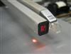
While there, I carefully cleaned the contacts of each trip, using the sandpaper again. I powered up the turntable and noticed that LED is not working. I tried to measure voltage across the LED's solderpoints but I'm not sure if one can do this.
Could it be that the carriage is not moving across a record if the LED is dead?
dauphine
|
|
-
-
Step1
 
- Joined on 07-06-2008
- Manchester
- Posts 961
|
Re: Beogram 4002 Series 5511 Restoration/Repairs
Led if you are refering to the slide carriage sensor is IR so will not be visible to the naked eye, but a video or some stills cameras can see it although my Canon stills camera doesn't due to an IR filter, my Sony video does!
run without the platter assembly when the arm drops (it will think there is a record,, only if ruler is in place otherwise drop manually) angle the arm manually so that the sled moves accros and visually check if the belt slipping / or there is something physically blocking the assembly etc..
You didn't mention if the arm lifts after things stop or if the arm moves toward the sensor arm without the cariiage progressing etc.. Important details!
|
|
-
-
Andre
- Joined on 12-04-2010
- Cape Town
- Posts 56
|
Re: Beogram 4002 Series 5511 Restoration/Repairs
Step1:
Led if you are refering to the slide carriage sensor is IR so will not be visible to the naked eye, but a video or some stills cameras can see it although my Canon stills camera doesn't due to an IR filter, my Sony video does!
run without the platter assembly when the arm drops (it will think there is a record,, only if ruler is in place otherwise drop manually) angle the arm manually so that the sled moves accros and visually check if the belt slipping / or there is something physically blocking the assembly etc..
You didn't mention if the arm lifts after things stop or if the arm moves toward the sensor arm without the cariiage progressing etc.. Important details!
Greetings, Olly
The arm carriage is free to move silently and on control demands. If "Start" is pressed, the carriage moves the arm to the lead-in groove on a record, the arm drops correctly and the record starts playing for only about 3 or 4mm of track one and stays there as if obstructed, but it is not.
At the moment, the arm's up and down function does not work, so I cannot lift the arm in start function and try another track. What does work is the left and right movement with the arm in the lifted position.
The belt is definitely not slipping as it is clean and a perfect fit.
What I have noticed is that when the arm descends on the start function, it drops correctly but as soon as the cartridge starts the lead-in groove, the arm position appears 'toe'ed-in' - angled to the left towards the sensor arm and no longer parallel with the sensor arm.
I have a Canon IXUS 40 digital camera and can try to photograph the IR beam.
Last night, with the ruler removed and with the platter spinning, I tried to measure voltage across the IR lamp but found no voltage. The top platter was removed at the time but I'm not sure if the arms were over the black part of the sub-platter.
As mentioned earlier, I spent a long time in setting up the suspension, as well as ensuring the 23mm distance between the top platter surface and the arm. There is absolutely no obstruction as all other side to side movement of the carriage functions silently without touching of scraping anywhere. All the carriage parts have already been thoroughly cleaned and re-lubricated, including the solenoids.
The only other clue I can give but I'm not sure if this has any bearing on the problem - is that the lit window for the 33.3 and 45rpm speeds above the control keys does not light up. Earlier, I checked each of the two original bulbs with a powersupply set at about 6V. They did come on but were extremely dim, so I replaced both lamps which lights up normally at 6V with my powersupply, but not during operation of the turntable.
If this IR lamp is dead or receives no voltage, will this be the cause of the problem, or is the problem with the angled inwards position of the cartridge arm?
Since the IR beam cannot be seen, what voltage should be across its solder points so I can check if the lamp is faulty or if there's no current to power it.
Regards
dauphine
|
|
-
-
Dillen
- Joined on 02-14-2007
- Copenhagen / Denmark
- Posts 5,008
|
Re: Beogram 4002 Series 5511 Restoration/Repairs
If the tonearm stops over the lead-in groove and lowers correctly, the IR and ruler is OK.
However, it sounds as if the carriage does not follow the tonearms movement.
Check the lamp in the tracking sensor housing at the base of the carriage.
It's a tiny filament bulb that should emit visible white light when playing.
It shines on a sensor with an interrupter in between that moves with the tonearm.
Martin
|
|
-
-
Andre
- Joined on 12-04-2010
- Cape Town
- Posts 56
|
Re: Beogram 4002 Series 5511 Restoration/Repairs
Hi Martin
I looked for that lamp until I'm cross-eyed and can't see it. Unless you are referring to the lamp under the wand next to the tonearm. That's working, as you can see from my pics.
The arm and all its functions are normal when start is pressed. It lowers gently in the lead-in groove and starts playing for about 1 minute and then gets stuck - so bad you can see the cartridge cantilever is pulled inwards. There is no obstruction at all. Everything is silent and smooth and I can traverse the carriage left and right with no hesitation.
Besides being 'stuck', there are still two other problems. The arm up/down function doesn't work and the red window above the stainless steel keypad is still dark - I don't know if this is related to the arm being immobile after playing only part of the first band of any record. I tried two other records by the way and this has the same result.
As you can see, I have again removed the ruler in my search for another lamp.
Regards
dauphine/andre
   
|
|
-
-
Dillen
- Joined on 02-14-2007
- Copenhagen / Denmark
- Posts 5,008
|
Re: Beogram 4002 Series 5511 Restoration/Repairs
The lamp sits inside the black square plastic housing right next to the brass damping cylinder.
You can see the arm for the light interrupter go into the housing where it moves when the
tonearm swings sideways.
The fact that you cannot see the light, confirms that something is fishy there.
The housing shields the sensor from ambient light but there will almost always shine a little
light out from the openings in the housing.
Lower left corner in the photo that was taken 20:54
Upper right corner in the photo that was taken 21:38
Martin
|
|
-
-
Andre
- Joined on 12-04-2010
- Cape Town
- Posts 56
|
Re: Beogram 4002 Series 5511 Restoration/Repairs
Ah, thanks again Martin.
For being stupid, I think I will go and have two dozen Copenhagens and go and stand in the corner for a while. and go and stand in the corner for a while.
But first, let me go and look at that lamp.
Best regards
dauphine/andre
|
|
-
-
Andre
- Joined on 12-04-2010
- Cape Town
- Posts 56
|
Re: Beogram 4002 Series 5511 Restoration/Repairs
Hi again, Martin
I removed the black cover and found the dead lamp epoxied in there, including its receptacle epoxied to the cover - and no way to remove that lamp without damage. So I had a look at my scrap 4000 series and found a similar lampholder there with a working lamp. I then measured the voltage across the solder points where the lamp must go on my 4002 and read 21.5Vdc. Would you know if the 4000 series lamp will be OK to use?
Regards
dauphine/andre
|
|
-
-
Søren Mexico
- Joined on 09-13-2007
- Mexico city
- Posts 1,621
|
Re: Beogram 4002 Series 5511 Restoration/Repairs
Andre: For being stupid, I think I will go and have two dozen Copenhagens and go and stand in the corner for a while.
Dont Andre, we are, compared to Martin and some other guys on the forum, all "stupid" or maybe just happy amateurs , keep going you are nearly there , keep going you are nearly there
Beosound 3000, BL 4000, BL 8000, BG 2404,BG 5000, BG CD50, Beocord 5000, BM 901, BM 2400, BM 4000, BV S45, BV 3702. There is nothing we cannot do, but a lot of things we don't want to do!!
|
|
|
|
|