|
Untitled Page
ARCHIVED FORUM -- April 2007 to March 2012
READ ONLY FORUM
This is the first Archived Forum which was active between 17th April 2007 and
1st March February 2012
Latest post 02-06-2011 9:45 AM by yachadm. 9 replies.
-
 01-12-2011 1:22 PM
|
|
-
 yachadm
 
 - Joined on 06-24-2007
- Jerusalem, Israel
- Posts 687

|
Workshop - BeoGram 6000 Quad - CD4 Demodulator Troubleshooting
This has been a very educational experience for me, as it is the first time I've had such problems with a CD4 demodulator, so I decided to share the troubleshooting process with everyone.
I have replaced all electrolytics and all trimpots, and a complete alignment with the JVC test record.
This took care of most of the sound-quality issues, but there is definitely a residual audible distortion on the left- channel.
All waveforms on the scope are as per SM, except for 1, and I presume that this is the cause of the distortion.
In the SM on page 6-2, you can see the 2 waveforms on the scope - the sine-wave off pin 2 of IC2, and the square-wave off pin 4 of IC2.
Regarding the sine wave only (pin 2) - on the left channel, it is slightly square, and on the right channel, it is a perfect sine wave.
My gut feeling is that the wave is cut off vertically, which reminds me of what rectifiers do to a signal.
Learn from the mistakes of others - you'll not live long enough to make them all yourself!
|
|
-
-
 yachadm
 
 - Joined on 06-24-2007
- Jerusalem, Israel
- Posts 687

|
Re: BeoGram 6000 Quad - CD4 Demodulator sine-wave adjustment
Here's a picture of the waveform - as is evident that pure sine-wave pattern, isn't.
On the right channel, it IS a perfect sine wave. 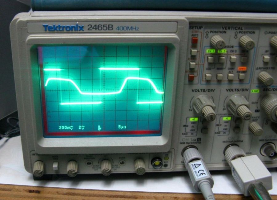
Learn from the mistakes of others - you'll not live long enough to make them all yourself!
|
|
-
-
 yachadm
 
 - Joined on 06-24-2007
- Jerusalem, Israel
- Posts 687

|
Re: BeoGram 6000 Quad - CD4 Demodulator sine-wave adjustment
It appeared that I had solved it when I replaced the tantalum decoupling caps with higher value electrolytics.
Here was my reasoning:
Distortion, right? OK, I've had lots of distortion problems with these CD-4 demodulators, and a recap generally solves it.
I always use Wima MKS2 polycaps as substitutes for 4.7uF and below. It just happens that all the original caps due for replacement on this PCB were either Tantalum or Ceramic.
All the 10uF and above (10 caps total) were replaced by Elna Silmic II - high-quality audio caps. These are all decoupling functions.
Bad move - I suddenly remembered reading that Polycaps are a great substitute for Tantalums, but Aluminium electrolytics are a poor substitute, and can induce unpredictable results. On some IC datasheets, manufacturers specify decoupling caps of x if tantalum and 10x if aluminium.
So, I tried not 10x, but 3x. After all this is vintage equipment.
All the 10uF's now became 33uF's, the 47uf's became 100uf, and the 100uF's became 220uF.
In retrospect, I also decided to not use the Silmics here - they are not audio path, so I used my favorite power caps - Nichicon HE and PW.
The waveform is now very nearly pure-sine, and the distortion is gone.
Obviously the power-lines were struggling with the smaller electrolytics.
No big deal, but worth keeping in mind if replacing tantalums (for decoupling) in these units.
BUT........
Learn from the mistakes of others - you'll not live long enough to make them all yourself!
|
|
-
-
 yachadm
 
 - Joined on 06-24-2007
- Jerusalem, Israel
- Posts 687

|
Re: BeoGram 6000 Quad - CD4 Demodulator sine-wave adjustment
Well, that turned out to be a temporary fix - ain't this fun!
The distortion is back, and I have to focus on the semiconductors. That waveform shape is a clue - it looks like a funny rectification. I patiently checked all the transistors - all appeared to be OK.
I then focused on the diodes - it has 14 OA90's. I unsoldered a leg, and checked on my ohmmeter - the leakage check on all of them is up way around 1/2 on the scale. I know that Germaniums leak, but this is well over what I've seen.
I talked to Martin Olsen about using Schottky's as a replacement here, but he recommended using AA143's as a substitute.
Here's what the diode leakage shows - and this is one of the better ones! 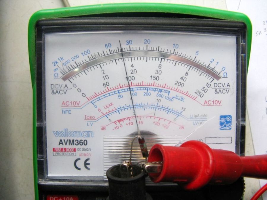
Learn from the mistakes of others - you'll not live long enough to make them all yourself!
|
|
-
-
 yachadm
 
 - Joined on 06-24-2007
- Jerusalem, Israel
- Posts 687

|
Re: BeoGram 6000 Quad - CD4 Demodulator sine-wave adjustment
So, after replacing all the OA90's in both the Left and Right channels with AA143's, here's what the result is.
Is it absolutely perfect? There is still a bit of flatness at the bottom peak, but the distortion is gone, and the sound is pretty amazing.
I'll take this as gospel truth that these diodes, when leaky, definitely affect the quality of the signal. 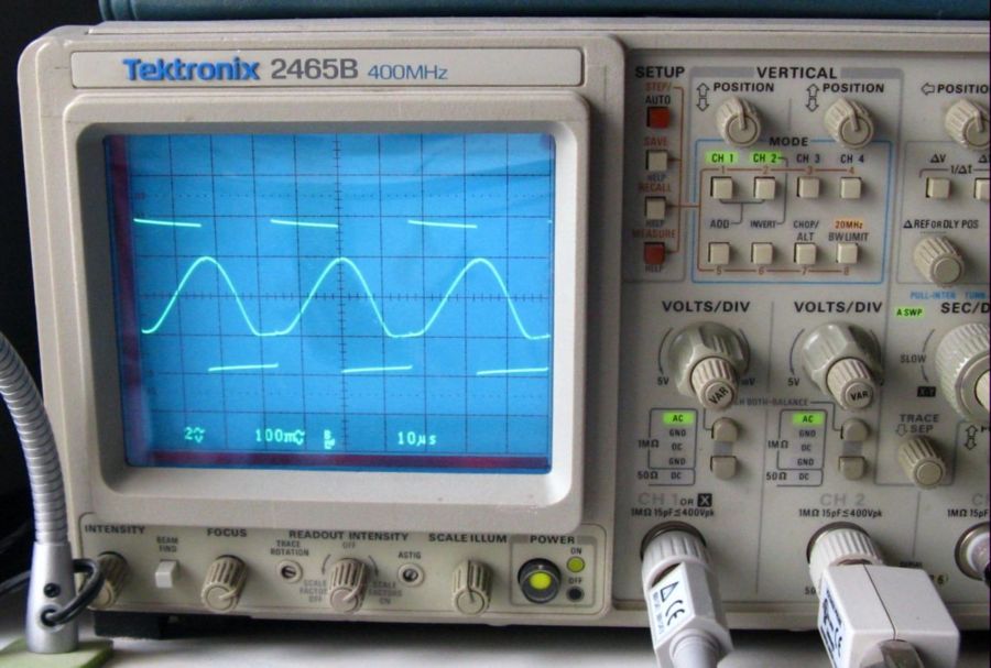
Learn from the mistakes of others - you'll not live long enough to make them all yourself!
|
|
-
-
 yachadm
 
 - Joined on 06-24-2007
- Jerusalem, Israel
- Posts 687

|
Re: Workshop - BeoGram 6000 Quad - CD4 Demodulator Troubleshooting
But I'm not finished yet - there is another issue with the 30KHz carrier signal detection....
The symptom of this problem was reduced volume in the right-channel.
This is the waveform off TR206 (right-channel) collector - nothing like the SM's picture, and look at the amplitude - less than 200mV p-p.
See the next post for what the Left channel looks like - 2V p-p, with the correct waveform according to the SM.
I adjusted R243 stop-to-stop with no improvement, either in amplitude (loundness of signal), or wave-form. 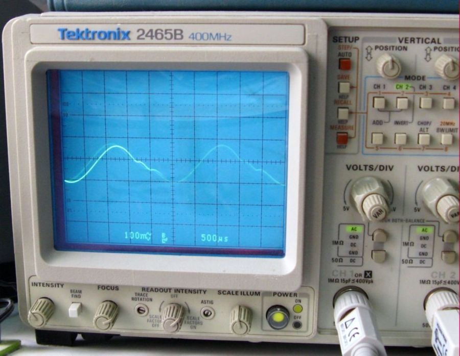
Learn from the mistakes of others - you'll not live long enough to make them all yourself!
|
|
-
-
-
 yachadm
 
 - Joined on 06-24-2007
- Jerusalem, Israel
- Posts 687

|
Re: Workshop - BeoGram 6000 Quad - CD4 Demodulator Troubleshooting
TR206 has 3 terminals - the Base, which has the Demodulator signal from Pin7 of IC202 (LM565), the Collector, which is the one showing the bad signal, and the Emitter.
Not having the circuit diagram for this PCB (this one is a single-storey version, as opposed to the much more common two-storey version with a little daughterbosrd mounted on top), and I don't believe that B&O published one for wide distribution (correct me if I'm wrong), I had to rely on the widely available SM, which B&O claims is very similar.
Well, in a way it is. Both PCB's use the LM565, and this one uses a discrete amplifier between Pin7 and TR206 Base, while the more common one uses a LM307 opamp instead.
There are also other circuit differences, which I discovered later.
Needless to say, I had my work cut out for me, trying to marry the other's circuit diagram to this PCB, and work out where the differences were.
The first part was easy - I checked the Demodulator Output signals between IC202 Pin7 and TR206 Base with the same path on the left side. All matched - so that was one third-of the circuit eliminated.
I decided to tackle the TR206 Collector's signal path next. It continues up to a1uF capacitor in a large blob, with 3 solder legs and there I found the problem. Those of you who know the vintage B&O's, are well aware of the generous leg lengths on the PCB undersides. Well, it appears that during my resoldering of all the joints, I had missed this long leg which had bent slightly, and was touching the long leg next to it, in another circuit. I cut the excess of both these legs, and tested again.
Voila!
Left channel and right channel identical (JVC Test disc - 30KHz signal) - just like the SM. 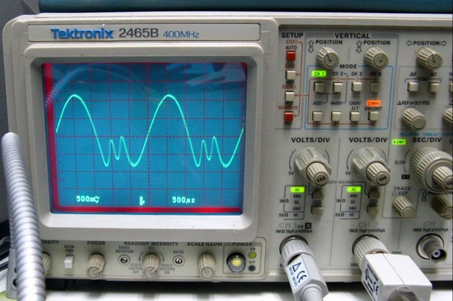
Learn from the mistakes of others - you'll not live long enough to make them all yourself!
|
|
-
-
 yachadm
 
 - Joined on 06-24-2007
- Jerusalem, Israel
- Posts 687

|
Re: Workshop - BeoGram 6000 Quad - CD4 Demodulator Troubleshooting
So now, I put on my favorite CD4 LP to check the real-world signal cleanliness. I don't know why, but Enoch Light's Spaced Out has a couple of tracks which sound very slightly distorted, even after completing the full calibration according to the SM with the JVC test disc.
Other CD4 LP's play right through without any distortion!
So, I have my own procedure to take care of this last little tweak.
This pic shows one of the LP's tracks taken off TR206 collector, AFTER completing all calibration according to the SM.
The residual distortion in the waveform is evident. The trick is to adjust R243 again, ever so slightly, to smoothen out the waveform, but not overdo it - too smooth, and the amplitude cuts down, resulting in reduced volume. 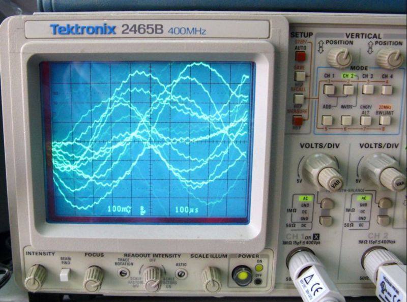
Learn from the mistakes of others - you'll not live long enough to make them all yourself!
|
|
-
-
 yachadm
 
 - Joined on 06-24-2007
- Jerusalem, Israel
- Posts 687

|
Re: Workshop - BeoGram 6000 Quad - CD4 Demodulator Troubleshooting
And this is the last step, the same LP track, showing a much smoother wave-form, and audibly pure.
Job completed - another Quad Turntable rescued!
As is evident, calibration of the CD4 PCB is impossible without an oscilloscope, but certainly possible without the Meguro CD4 generator, as long as the JVC Test disc is on hand. 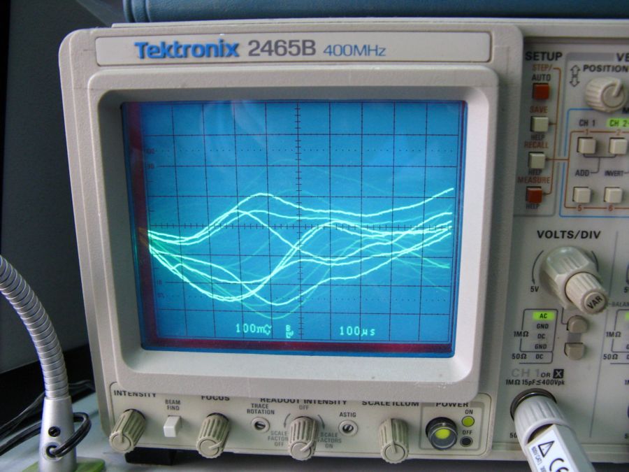
Learn from the mistakes of others - you'll not live long enough to make them all yourself!
|
|
Page 1 of 1 (10 items)
|
|
|