I'm working on a BG6000 with AC motor.
The machine does play records perfectly in every way, except that it runs very hot.
Because it appears to do all it's supposed to, the SM troubleshooting guide appears to be useless in this case.
The voltages off the bridge (SM in brackets) are OFF 40.5 (41), ON 33.9 (35), V 23.7 (31).
Yes, when the arm is down (ie playing), voltage is leaking somwhere - 7V has run off somwhere. Within 5 minutes, the whole machine is hot to touch!
I've done a lot of troubleshooting, with no solution yet.
The main 22.8V rail is OK at all points, but R1 - I replaced it with a 2.2K 3W unit - gets HOT!
All diodes (including Zeners) appear to check OK.
All transistors also appear to check OK.
I have replaced all electrolytic and tantalum caps, and the 6 trimpots, and few out-of-spec resistors on the main control PCB.
Unless I've missed something, as far as I can see, the components which are on board are all OK.
I have disconnected the CD4 PCB. No mods (such as LED's etc) have been done yet.
I've gone over the main PCB witha magnifying glass, looking for solder whiskers to see if there are any inadvertent connections (normally during soldering, I am extremely careful with this issue anyway), but I could not find anything.
I also double-checked trimpot R35 - the detector adjustment - it warns of a load danger, but I cannot see any voltage change when adjusting this.
The solenoid is measuring 9.2 ohms, 3.2mH, and indicates 2 yellow lights on the Blue-ring tester, so unless someomeone has another solenoid to corroborate results, it appears OK.
I concentrated troubleshooting in 2 main areas:
1. The Solenoid circuit - TR14, TR15, TR16, and 0TR4 - all the step-up voltgaes on the Circuit Diagram check out OK.
2. The detector arm circuit - TR10 11, 12, 13 is where I'm looking now.
I replaced TR11 BC337 - it was very hot, with BC639, and D10 15V Zener, but I still have only 8.4V (12V) at TR11 collector. D9 (Z6.2) checks OK - I do have 6.2V at TR11 base.
TR9 Base is 0.62V (0.7), and Collector is 2.85 (3.0). I do not get any of the scope forms for these 2 positions (or for TR10 Base (OK at 22.8V), as in the circuit diagram, rather I get a nice straight stable voltage line.
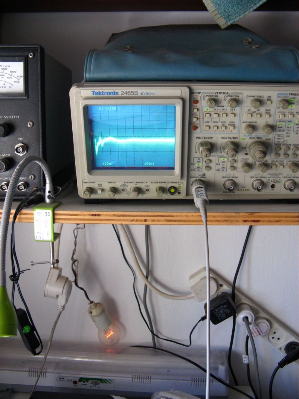
Un the picture, 2 things are important -
1. see the incandescent lamp illuminated - that's the voltage leaking only when the arm is down (When the arm is up, the lamp is not illuminated) - The BG6000 is connected via that series lamp to save fuses!
2. The scope form is of the detector arm 0PH1 - it is 0.1V, not changing voltage, only form. When the arm's down, that's the form. I'm not sure if that's what it's supposed to look like.
Any ideas where to go for this leakage?
The seller advertised this in Perfect Working condition, and according to a quick check, it was, until it's been on a few minutes and heats up!
Menahem

Learn from the mistakes of others - you'll not live long enough to make them all yourself!