|
Untitled Page
ARCHIVED FORUM -- April 2007 to March 2012
READ ONLY FORUM
This is the first Archived Forum which was active between 17th April 2007 and
1st March February 2012
Latest post 11-02-2009 4:48 AM by yachadm. 11 replies.
-
 08-30-2009 5:27 AM
|
|
-
 yachadm
 
 - Joined on 06-24-2007
- Jerusalem, Israel
- Posts 687

|
BeoMaster 5000 restoration - still some issues
I have almost completed a full restoration of a BeoMaster 5000 - type 2322.
All electrolytic and tantalum caps were replaced mostly by Panasonic FC's and FM's, and a couple of Nichicons and WIMA's , and all trimpots were replaced by Bourns 3352 Cermet units. The 2 large Power cans - 10,000uF 63V - were replaced by Cornell Dubilier units.
On initial power up, everything appeared normal.
I adjusted the DC trimpot for 5V, and the No-load current trimpots for 11mV.
I haven't got to the RF alignment yet, as there are 2 voltage issues here
1. The service manual calls for setting AF level - volume trimpots 3R141 and 3R241 to 4.2VAC, but I cannot set them to less than 5.8VAC - yes, I used the correct trimpots 22Kohm (even though the parts list says 22ohm)!
2. The second issue is the cooling-fan motor - it is not operating - the system shut down after about 2 minutes, and the amp heat-sink fins were hot.
When does the motor start operating, or does it operate permanently? If not permanently, what is the trigger to start operation?
Below is a photo of the restored interior - the clear plastic shield on the right is not installed yet, until the alignment and adjustments are 100% complete.
Menahem 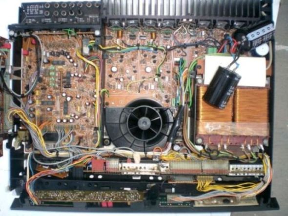
Learn from the mistakes of others - you'll not live long enough to make them all yourself!
|
|
-
-
Dillen
  - Joined on 02-14-2007
- Copenhagen / Denmark
- Posts 5,008

|
Re: BeoMaster 5000 restoration - still some issues
Hot heatsinks generally points to too high idle currents or too high power consumption depending on
whether warmest at the left, center or right side of the heatsink.
I've seen cases where one of the output stage transistors had poor thermic contact
to the cooling fin.
Using an IR thermometer, I checked the temps of the individual transistors and
found one to be considerably higher than the other three after playing only a couple of minutes.
The old cooling paste was not applied as plentyful as with the others and had
(therefore) dried out.
The blower circuit senses temp. on the cooling fin by means of
a little NTC or PTC placed there.
It will not run until quite warm and will not be able to "catch up" with a
too high idle current.
Martin
|
|
-
-
yachadm
- Joined on 06-24-2007
- Jerusalem, Israel
- Posts 687
|
Re: BeoMaster 5000 restoration - still some issues
Thanks Martin,
I disassembled the entire rear heatsink piece, cleaned off all the old hardened paste, and cut new heatsink film for each transistor.
I'll let it run now, and see what happens.
The little NTC on the heatsink is a 330Kohm unit, currently measuring 247Kohm - clearly visible in the picture. There is also a 15ohm PTC on the motor PCB, currently measuring 15ohm.
Any ideas on the AC voltage discrepancy on the volume trimpots? 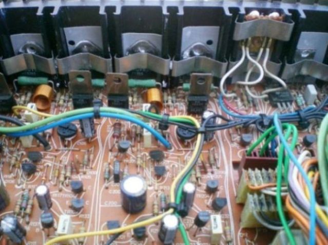
Learn from the mistakes of others - you'll not live long enough to make them all yourself!
|
|
-
-
yachadm
- Joined on 06-24-2007
- Jerusalem, Israel
- Posts 687
|
Re: BeoMaster 5000 restoration - still some issues
Right on - the fan's working.
Now that I understand that the NTC on the heatsink is the trigger, I applied my heatgun to the heatsink at the NTC's location. Within a few seconds, the fan started up.
So, the circuit is confirmed functional - that problem's solved!
I'll recheck the No-load current again.
Now, any ideas about the AC voltage on the volume trimpots?
Menahem
Learn from the mistakes of others - you'll not live long enough to make them all yourself!
|
|
-
-
Dillen
- Joined on 02-14-2007
- Copenhagen / Denmark
- Posts 5,008
|
Re: BeoMaster 5000 restoration - still some issues
So far so good.
Are you sure you measure correct ? (AC rms or pp)
As I see it, the most important thing is to keep away from distortion.
How is the sound ?
Martin
|
|
-
-
yachadm
- Joined on 06-24-2007
- Jerusalem, Israel
- Posts 687
|
Re: BeoMaster 5000 restoration - still some issues
Sound is very nice when playing at relatively low volume, and it does not cut out to Standby, but if I up the volume to about 3, it will cut out to Standby after about 2 minutes, and the fan does not start up.
There is another problem - the RL1 relay on the PSU board is faulty - I took it out and cleaned the contacts, but one side is still not making contact - so now I need another relay. Please confirm it is in-fact a 6V normally-closed relay. But how many amps should it be, if I can't get an original replacement?
Menahem 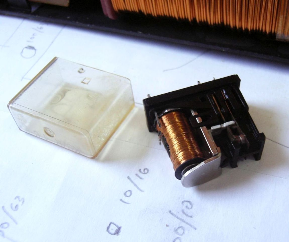
Learn from the mistakes of others - you'll not live long enough to make them all yourself!
|
|
-
-
Dillen
- Joined on 02-14-2007
- Copenhagen / Denmark
- Posts 5,008
|
Re: BeoMaster 5000 restoration - still some issues
Standard relay. Nothing fancy.
8 Amp if I remember correctly.
Martin
|
|
-
-
yachadm
- Joined on 06-24-2007
- Jerusalem, Israel
- Posts 687
|
Re: BeoMaster 5000 restoration - still some issues
Ok thanks - I'll get a couple.
In the meantime, this quiescent current adjustment is bothering me. In the BM5000 SM, it shows the 11mV measurement to be taken across the TWO bias resistors (in series) on each channel. I must admit that this is the "newest" BeoMaster I have restored, all others being of 1960's and 1970's vintage (and I like the older ones better).
On the older BM's, the measurement is taken across ONE bias resistor only.
Is this a "for sure" that 11mVDC is across the TWO resistors on the BM5000?
Menahem
Learn from the mistakes of others - you'll not live long enough to make them all yourself!
|
|
-
-
Dillen
- Joined on 02-14-2007
- Copenhagen / Denmark
- Posts 5,008
|
Re: BeoMaster 5000 restoration - still some issues
I've wondered myself but yes, it is correct.
Other amplifiers (I seem to remember the Penta's and also the BM8000) is given the same way.
Having said that, to prevent crossover distortion, I like to set the idle current around 8mV across ONE emitter resistor.
That's a little bit higher than what's stated in the manual but it provides a greater margin, compensates for different "aging" of
the output stage transistors and doesn't build up heat.
Also, since your cooling fins do get hot, check if one (or both) of the amplifiers are self-oscillating.
I've seen it a couple of times that BM5000 amplifiers have done a melt-down for no (other) apparent reason.
We had a thread about this a while back, ending quite amusing as I remember it.
Martin
|
|
-
-
yachadm
- Joined on 06-24-2007
- Jerusalem, Israel
- Posts 687
|
Re: BeoMaster 5000 restoration - still some issues
OK, I'll set 8mV across one resistor.
At the risk of sounding ignorant, how do I check for self-oscillation? That's a new one for me.
OK, I read the BM7000 post, and I see your comment about putting the scope on the signal path and power rails, so that's understood, unless you want to add something else.
However, I'm going to wait on any further testing, until I get a new relay in there - the oscillation could be coming from that - one one pair of contacts, it's showing 2.6ohms (closed), and on the other 0.86ohms - definitely not acceptable.
On ebay, I found a Finder 4462 6V 10amp DPDT NC, which will fit right in the original PCB slots, so it might take a week or so to get here.
Menahem
Learn from the mistakes of others - you'll not live long enough to make them all yourself!
|
|
-
-
Dillen
- Joined on 02-14-2007
- Copenhagen / Denmark
- Posts 5,008
|
Re: BeoMaster 5000 restoration - still some issues
Yes, the scope will tell.
But I agree that the idle current and power relay will have to be good first.
Martin
|
|
-
-
yachadm
- Joined on 06-24-2007
- Jerusalem, Israel
- Posts 687
|
Re: BeoMaster 5000 restoration - still some issues
OK, up to the last stage!
New Schrack relays installed, all voltages adjusted on trimpots according to the SM.
One last niggling observation - when measuring from TP100 and TP200 (the emitter resistors) to Chassis Earth, there is 66mVDC on the right channel, and only 33mVDC on the Left. There is no spec for this in the SM, but this discrepancy could be the reason why the BM shuts down with volume over 4.6.
Any and all ideas very welcome!!!!
Menahem
Learn from the mistakes of others - you'll not live long enough to make them all yourself!
|
|
Page 1 of 1 (12 items)
|
|
|