|
Untitled Page
ARCHIVED FORUM -- April 2007 to March 2012
READ ONLY FORUM
This is the first Archived Forum which was active between 17th April 2007 and
1st March February 2012
Latest post 02-20-2012 4:42 PM by sonavor. 215 replies.
-
-
 sonavor
  - Joined on 02-13-2011
- Texas
- Posts 193

|
Re: Beomaster 6000 Refurbish
Thanks for the encouragement. The information in the links look promising. I will have to dig into the potentiometer and check all of those connector solder joints later today. I did check the voltage on the reset line and it is measuring 4.9vdc.
-Sonavor
|
|
-
-
Step1
 
 - Joined on 07-06-2008
- Manchester
- Posts 961

|
Re: Beomaster 6000 Refurbish
Hmm that is not really what you wanted to see. I would expect to see closer to 5v but I really don't think 4.9v would be problematic, Where did you place the meter negative?
The fact reset is high, means that the processor should be running ok, at this point try shorting test points and see if pin 39 drops to zero volts (not that it makes a great deal of difference!). Are you sure you got the right pin? Also check that the micro is getting a supply by testing accross pins 20 & 40.
I would check all the work you have done in this area, and double check the electros (did they go in the right way?) and look for bridges, dry joints etc. you really need to download the service manual if you haven't done so already.
What are you taking in the way of antistatic precautions?
|
|
-
-
tournedos
  - Joined on 12-08-2007
- Finland
- Posts 5,808
|
Re: Beomaster 6000 Refurbish
 Step1: Step1:The fact reset is high, means that the processor should be running ok
Not necessarily; the reset signal needs to come up with a certain speed and timing in relation to the supply voltages, or the processor might not reset properly. Just having it high at a later time isn't enough.
The reset circuits in many B&O products are implemented in a somewhat odd and complicated way for whatever reason (compared to what the chip manufacturers specify) and aging components may cause them to not work properly. Could well be a problem with the trimmer now that the circuit board has been disturbed.
|
|
-
-
sonavor
- Joined on 02-13-2011
- Texas
- Posts 193
|
Re: Beomaster 6000 Refurbish
When I get back to it this afternoon I plan to monitor the reset line with an oscilloscope so I can see activity on that signal. I did first check the voltage from pin 40 V+ and pin 20 gnd. It was also 4.9vdc. After that I checked the reset line...but only with a DVM to see what the current state was. Dillen also mentioned the trimmer involved with the reset logic so after I see what the scope reveals I might have to change that out or try to re-adjust it. I am also going to check all of the board connector solder points.
-Sonavor
|
|
-
-
sonavor
- Joined on 02-13-2011
- Texas
- Posts 193
|
Re: Beomaster 6000 Refurbish
On the antistatic precautions - I didn't wear a ground strap on my wrist to my anti-static mat. However, I did make sure I touched chassis ground before touching the board. The only components I removed on the board were the IC8 and two electrolytic caps. I double-checked the caps first thing and they are in with the correct polarity. I haven't done a complete inspection of the solder joints yet. I do have the manual.
- Sonavor
|
|
-
-
-
-
Step1
- Joined on 07-06-2008
- Manchester
- Posts 961
|
Re: Beomaster 6000 Refurbish
sonavor:
I couldn't wait to check the signals on a scope so I did a quick measurement over lunch. Here is a picture of what my oscilloscope caught monitoring the micro-computer - IC4 on the 02 Module. The red trace is the probe connected to pin 40 (Vp) and the yellow trace is the probe connected to pin 39 (reset). Should there be more of a delay when the reset line comes up? Also note - in my earlier posting where I said the DC voltage was 4.9...it is actually 4.98.
Looks about right, I think the best thing you can do is to follow the proceedure to recalibrate the reset circuit, after replacing the preset. The reset could be opening up a little prematurely. Have you tried shorting the reset pins? - base of transistor 2tr5 shorted to ground?
I wouldn't worry about the fault signal timing wise, this event happens before the reset signal goes high so will not effect the processor. however not sure I like the fact it is going negative for a short period. Anyone esle with other opinions?
@Mika yes I guess more modern processors have brownout detect which is what this circuit effectively is. Now, regards the reset signal I would think a late reset pulse should be fine, as the instructions are only halted by the presence of a reset signal, the processor is still active internally according to the manual. I wonder if too early then this could be an issue?
|
|
-
-
sonavor
- Joined on 02-13-2011
- Texas
- Posts 193
|
Re: Beomaster 6000 Refurbish
I ran a test where I forced a reset - connected the base of TR5 (TP1) to the ground of the board. I was monitoring the reset line (Pin 39 of IC4) and saw it go to its "0" state. Nothing changed during or after the reset regarding the display. It remained at "P". Is there an output pin for IC4 that I can monitor to see if the reset line affected it? Something to tell if IC4 is functioning?
-Sonavor
|
|
-
-
sonavor
- Joined on 02-13-2011
- Texas
- Posts 193
|
Re: Beomaster 6000 Refurbish
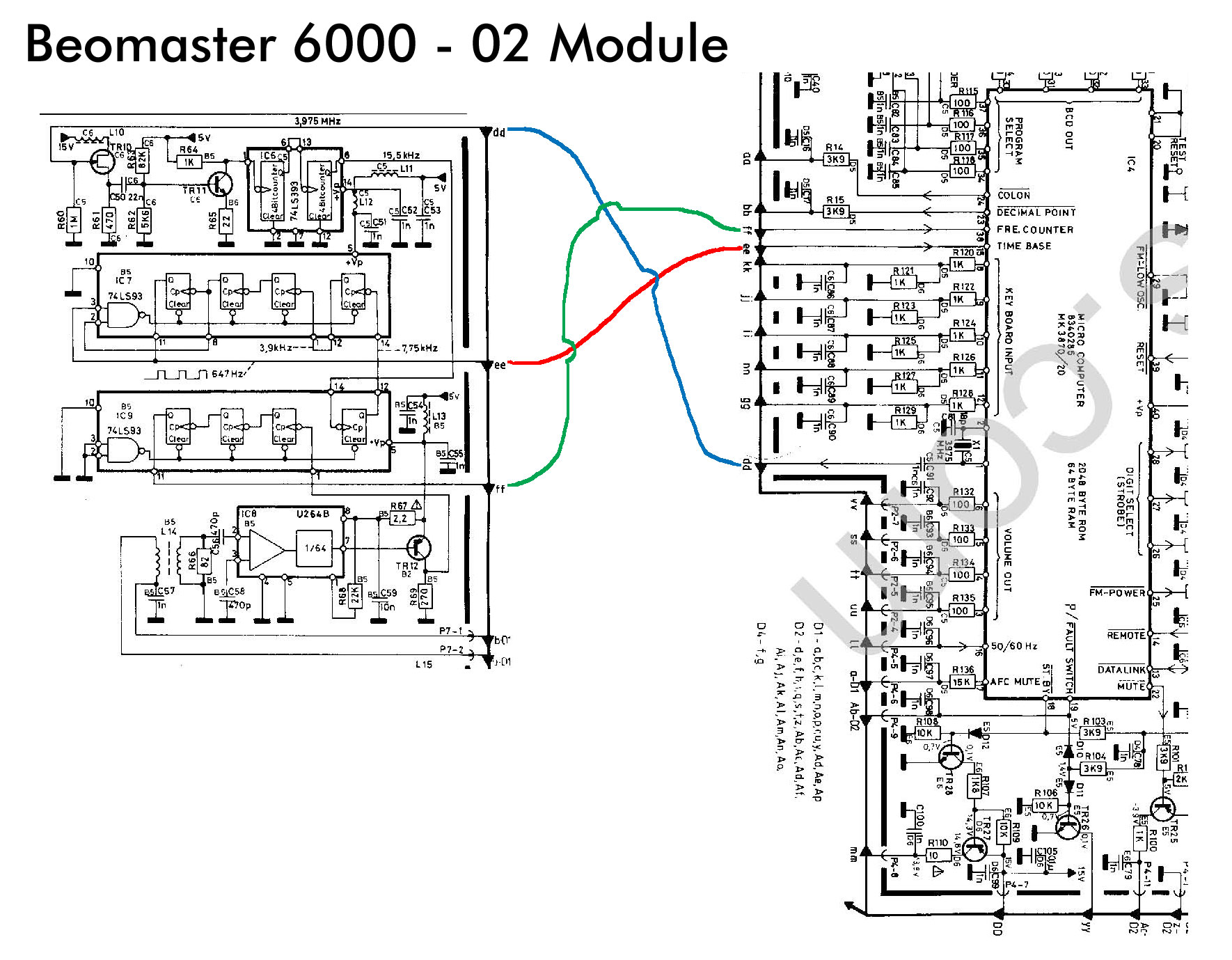
I think I have found the problem. The IC4 MicroComputer has no clock. IC4 pin 15 is supposed to be the timebase for the processor and it is dead. So without a clock nothing can change state. Here is a picture of the 02 Module circuitry involving the timbase and microcomputer. The red line is the connection that is supposed to be supplying the clock signal to IC4.
|
|
-
-
-
sonavor
- Joined on 02-13-2011
- Texas
- Posts 193
|
Re: Beomaster 6000 Refurbish
I have studying the unknown IC and the wiring it uses to the trace side. It looks like it is a replacement for IC6 (which is underneath it). IC7 and IC9 are 74LS93 4-bit binary counters (Decade Counter; Divide-By-Twelve Counter). IC6 is a 74LS393...slightly different? The replacement on the little home-made board is a 74LS74AN Dual Edge Flip-Flop. The pin layout on the IC is different from the 74LS393 so that is why the mod with the board was made.
Now I need to determine what exactly are the bad components in the clock signal circuitry.
It appears Mouser carries 74LS93 and 74LS393 chips so I will look at restoring the original layout.
-Sonavor
|
|
-
-
-
tournedos
- Joined on 12-08-2007
- Finland
- Posts 5,808
|
Re: Beomaster 6000 Refurbish
sonavor: I think I have found the problem. The IC4 MicroComputer has no clock. IC4 pin 15 is supposed to be the timebase for the processor and it is dead. So without a clock nothing can change state.
Not quite correct - that signal is apparently just something the software uses for timing purposes. The actual clock oscillator is in the processor, on pins 1&2 around X1 and supplies the 3.something MHz clock to both to the processor itself and the divider circuitry you're working on (via the blue trace you've drawn). Did you have anything there?
I believe the processor is actually running as the "P" display wouldn't come up at random every time, it is probably some error diagnostic. Anyway if the divider isn't working, you'll need to fix it.
|
|
-
-
Step1
- Joined on 07-06-2008
- Manchester
- Posts 961
|
Re: Beomaster 6000 Refurbish
This little board is an official b&o mod designed to reduce the burden of the CPU needed to read the frequency pulses from the radio section, it has nothing to do with the processor clock.
You should be able to see a clock signal on the pins Mika suggests above, if not, I am afraid it is more than likely your processor has failed.
|
|
-
-
sonavor
- Joined on 02-13-2011
- Texas
- Posts 193
|
Re: Beomaster 6000 Refurbish
Yeah, I see that now. I checked the oscillator and pin 1 of IC4 and there is a signal there. So with a clock signal going to IC4 and +5V power, the processor does not respond to the reset line. The display output is stuck on "P". I think IC4 is dead. Is the IC4 processor component still available or is this receiver now a spare parts unit?
-Sonavor
|
|
-
-
sonavor
- Joined on 02-13-2011
- Texas
- Posts 193
|
Re: Beomaster 6000 Refurbish
Here is what I make of the Beomaster 6000 - 02 Module frequency counter circuit. The top frame is from the service manual schematic. The bottom frame is from tracing the paths on my BM6000 with the 74LS74AN flip-flop on the 8002562 mod PCB. Note that I didn't include all of the +5V filtering components on my schematic. I also didn't show all of the other connections to the IC4 processor...just the ones to and from the frequency counter.
Looking at the circuit schematic now, it appears that I would only see clocking signals out of the IC6, IC7, IC9 and the additional IC when the FM tuner was in play? So that circuitry might all be okay. I was thinking (hoping) that the fact I wasn't seeing any output there that it might be causing my problem. I don't think that is the case now. It appears that the processor (IC4) is dead and so there is no FM or any other function alive except for the power supply. I am not giving up though. I will put this one a way for a while until I can locate a replacement IC4 component. 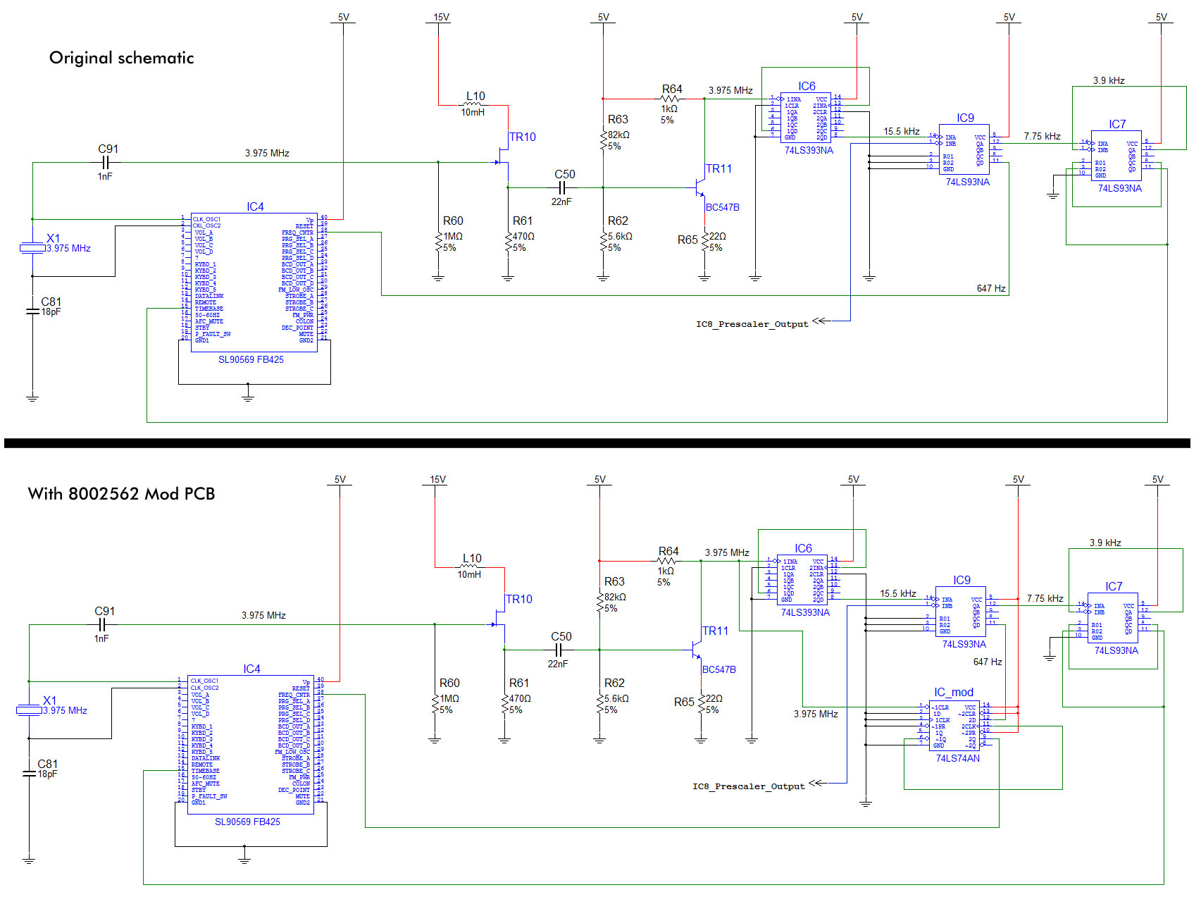
|
|
-
-
-
sonavor
- Joined on 02-13-2011
- Texas
- Posts 193
|
Re: Beomaster 6000 Refurbish
I do get a triangular type 3.975MHz signal from the oscillator (on one side, the other side was 5v I think). It isn't a nice, perfect triangle wave. I'll try and get a picture of it from the oscilloscope. But even so, I think there is a lot of evidence indicating the processor is dead. If so, I had to have zapped it with static when the board was out of the unit. The worst part about that is that I do have an anti-static mat and wristband but I wasn't wearing the band. You can bet I won't make that mistake again.
In your Beomaster 6000 repairs, have you ever had to replace the processor chip? Is the only way to get one to find a broken BM6000 (with a good IC4 chip)?
-Sonavor
|
|
-
-
tournedos
- Joined on 12-08-2007
- Finland
- Posts 5,808
|
Re: Beomaster 6000 Refurbish
sonavor: I do get a triangular type 3.975MHz signal from
the oscillator (on one side, the other side was 5v I think). It isn't a
nice, perfect triangle wave. I'll try and get a picture of it from the
oscilloscope.
Never mind the waveform over there -
coming directly off the crystal, it won't be a clean signal, and even
the load from your oscilloscope probe may alter it. It's very high
impedance, that's why there is a FET (TR10) and another transistor
amplifying it before it is fed to the digital circuits. There are a
number of intermediate frequencies specified on the schematic, go
through them instead starting from the amplified 3.975 MHz at the
collector of TR11, where you should see a clean TTL level square wave.
The dividing circuitry is completely dumb and will run regardless of
what the processor is doing.
The processor is unfortunately a mask programmed device with the
program code fixed in ROM, so the only source for it is another BM6000.
|
|
-
-
-
sonavor
- Joined on 02-13-2011
- Texas
- Posts 193
|
Re: Beomaster 6000 Refurbish
So you are saying that if the waveform doesn't make it through the digital circuit that would cause the processor to not function properly?
-Sonavor
|
|
-
-
Step1
- Joined on 07-06-2008
- Manchester
- Posts 961
|
Re: Beomaster 6000 Refurbish
Yes, the main oscillator is used for the internal timers to count the tuner pulses, and then that very signal is prescaled to time the processor - this is why I asked if you had a main clock, start at the roots, so to speak! If there is a clock at the gate of the fet, then there should be a clock at pin 15, if not find out where it is getting stuck.
Are you using x10 probes? I get a fairly nice sinus wave with processor clocks generally, and that is with a no thrills scope and standard x10 scope lead (I would really love a digital scope to capture waveforms though!).
|
|
-
-
sonavor
- Joined on 02-13-2011
- Texas
- Posts 193
|
Re: Beomaster 6000 Refurbish
I have the little 8002562 mod PCB out right now but one reason I removed it was because I wasn't getting any clock signal at the processor pin 15. I have ordered replacement ICs for the counters (they were pretty cheap - from less than a dollar to just over two dollars). They should arrive tomorrow and I will get the 02 module back together. Then we'll see what happens.
My scope probes are switchable between x1 and x10. I switched between them to get the best image I can use. I am using a 25MHz digital dual-trace scope. It is Chinese made (Owon brand) and it works good enough for me. I always wanted a Tektronix or HP but those are just too expensive for my budget. A friend of mine suggested the Owon to me and it has been a nice tool to have. They sell new for less than $300.
|
|
-
|
|
|