|
Untitled Page
ARCHIVED FORUM -- April 2007 to March 2012
READ ONLY FORUM
This is the first Archived Forum which was active between 17th April 2007 and
1st March February 2012
Latest post 01-06-2012 7:44 PM by sonavor. 38 replies.
-
 12-18-2011 2:23 AM
|
|
-
 sonavor
  - Joined on 02-13-2011
- Texas
- Posts 193

|
Beomaster 4000 (type 2408) Circuit Differences
Here is another refurbish project on the Beomaster 4000. As I have been following Søren's (Mexico) project I have been preparing to begin mine. Part of the preparation was to get a capacitor kit from Dillen which I now have. My goal is to refurbish my first BM-4000 so that it will be a dependable receiver I can use every day.
In my case, I have two Beomaster 4000 units that I am wanting to restore. I bought both of them in the past year - buying just one at first, then getting a second later on a pretty good deal. Both of the units were working where I could get sound. The second one has some switch issues and the tuning section appeared to not stay in stereo mode. The first unit needs the slider switches cleaned and it has the problem where the transformer vibrates. To make things more interesting, I later bought two more units as repair units. One of these came without a transformer. The other one has a transformer but it has a short - and consequently, some burn marks on at least one PCB. Both of those repair units were dirt cheap so I had to buy them for possible spare parts. It turns out that they are also useful in comparing the wiring between the four units.
I decided to begin with the BM-4000 that I felt was in the best shape. That is the one with the vibration in the transformer. Here is what the wood cover looks like and is another reason why I want to get this one done first.

In looking at the power section I saw the crowded little piece of circuit board that has the two 180 ohm, 1W resistors -

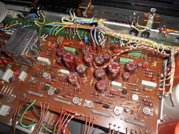
The resistors look pretty well aged. The way that whole assembly looks kind of odd to me but I noticed that Søren's was the same way. Now for something interesting. In my other Beomaster 4000 unit that I want to refurbish, this same circuit is implemented differently. The second unit has the same resistor and capacitor components but they are mounted on a nice PCB numbered: 8002135 Here is a picture -

I figured that the difference may be because of a difference in model type. However, both units are marked as Beomaster 4000 type 2408. Another difference between the two units is in the main PCB - 8002095. That PCB has the same 8002095 number on both units but the actual PCB traces are different. I will show some pictures of those differences a little later. The other thing that is interesting is that while my two BM-4000 units implement the resistor/capacitor mounting for the above circuit differently, the actual circuit and component values are the same. However, that actual circuit is not the same as the schematic that is included with each unit. I will post those differences as well.
-sonavor
|
|
-
-
sonavor
- Joined on 02-13-2011
- Texas
- Posts 193
|
Re: Beomaster 4000 (type 2408) Circuit Differences
The first differences I want to show is in the schematics
Here is my redraw of the circuitry in the original schematic drawings included with the BM-4000

Now here is the schematic as I traced out of my first BM-4000 (the one with the small piece of PCB material like Søren's) -

The first thing to notice here is that the 8.2k ohm resistors are replaced with different values. Not only that - the original schematic has the center node between two 8.2k ohm resistors connecting to a node between two diodes. The actual circuitry on this small resistor board and the 2002095 PCB separates the nodes between the diodes. On the actual 2002095 board in my BM-4000, I can see that a board rework was done (during manufacturing I guess) that separates the connection between the two diodes. In my second BM-4000, the 2002095 PCB is layed out differently and the diodes are separated in printed circuit. Here is the same circuit for my second BM-4000. The difference between this and my first unit is that the resistor/capacitor components are shown on the undocumented 8002135 PCB -

|
|
-
-
sonavor
- Joined on 02-13-2011
- Texas
- Posts 193
|
Re: Beomaster 4000 (type 2408) Circuit Differences
Here is a picture of my first BM-4000 unit small resistor/capacitor board that connects to the power capacitors and the 8002095 PCB -

Now here is the same circuit from my second BM-4000 that has this circuit placed on the PCB designated 8002135

|
|
-
-
sonavor
- Joined on 02-13-2011
- Texas
- Posts 193
|
Re: Beomaster 4000 (type 2408) Circuit Differences
Here is the original schematic PCB layout for 8002095. The two pairs of diodes (579 and 582, 489 and 492) are highlighted. Notice that the connection node for each pair shows them connected per the schematic drawing -

Looking at the node between 582 and 579 on my first BM-4000 unit, here is that picture -

You can see that the connection trace has been cut. I believe this must have been a mod to this 8002095 PCB either at the factory or by a B&O authorized repair shop.
This next picture is the same point on the 8002095 PCB for my second BM-4000. This is the one that has a new 8002095 PCB layout -

In the BM-4000 units I have with the 8002135 resistor board and the updated 8002095 layout, the connection wires between the 8002095 board and the resistor board are different colors on the following: The green wire is equivalent to the black/white wire.
|
|
-
-
sonavor
- Joined on 02-13-2011
- Texas
- Posts 193
|
Re: Beomaster 4000 (type 2408) Circuit Differences
Here are the component sides of my two BM-4000 (type 2408) unit's 8002095 PCB -
My first unit's 8002095 PCB -

My second unit's 8002095 PCB -

The first thing I noticed was that this second unit's 8002095 PCB has an additional two trim pots in the bottom, center of the board.
The original BM-4000 schematic that comes with each unit shows just two trim pots. That, along with the fact that my first BM-4000 unit has the mod to separate the two pairs of diodes seems to indicate my first BM-4000 was an earlier model than my second BM-4000. Plus, my second unit has the updated 8002135 board for the power supply resistors.
My first unit's (serial number?) NO. on the back is 145047. My second unit's NO. is 876039.
A confusing thing about those numbers is that on my two "parts" units I bought have NO. 274152 and 1239044. On those two units, the 274152 circuits are like my 145047. But the 1239044 are like my 876039. I'm not sure I trust the internals of those "parts" units though. It looks like attempts have been made on those before. So it is possible that they have parts that were changed out.
|
|
-
-
PDH
  - Joined on 03-23-2009
- Denmark
- Posts 7

|
Re: Beomaster 4000 (type 2408) Circuit Differences
Maby this can help a little
Per H
|
|
-
-
Søren Mexico
 
 - Joined on 09-13-2007
- Mexico city
- Posts 1,621

|
Re: Beomaster 4000 (type 2408) Circuit Differences
Per H is faster than I am, but the only update on my BM are the resistors 490,491.
Beosound 3000, BL 4000, BL 8000, BG 2404,BG 5000, BG CD50, Beocord 5000, BM 901, BM 2400, BM 4000, BV S45, BV 3702. There is nothing we cannot do, but a lot of things we don't want to do!!
|
|
-
-
Søren Mexico
- Joined on 09-13-2007
- Mexico city
- Posts 1,621
|
Re: Beomaster 4000 (type 2408) Circuit Differences
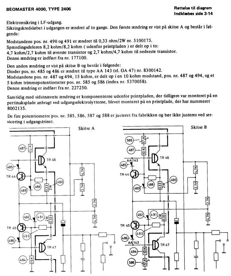
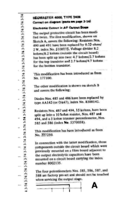
Here the update text in English
Beosound 3000, BL 4000, BL 8000, BG 2404,BG 5000, BG CD50, Beocord 5000, BM 901, BM 2400, BM 4000, BV S45, BV 3702. There is nothing we cannot do, but a lot of things we don't want to do!!
|
|
-
-
-
sonavor
- Joined on 02-13-2011
- Texas
- Posts 193
|
Re: Beomaster 4000 (type 2408) Circuit Differences
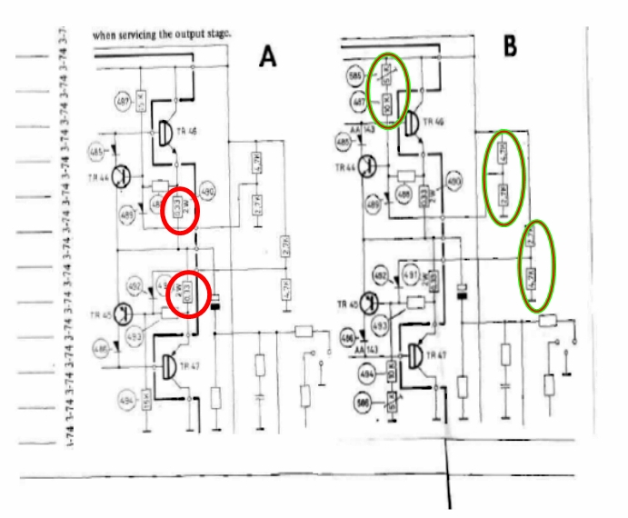
Okay, so I think I understand it -
Diagram A shows the update from the original BM-4000 type 2406 to the ones I have (which are type 2408).
Diagram B shows an update of type 2408 for units with serial numbers after 227250. That update is what I have on my second unit.
Thanks a lot Søren,
sonavor
|
|
-
-
Rich

- Joined on 07-10-2010
- Orlando, Florida, USA
- Posts 1,089
|
Re: Beomaster 4000 (type 2408) Circuit Differences
This is what Martin/Dillen said about my BM4000's amplifier board: "BTW, interesting to see that you have the amplifier version with the four extra trimmers."
Current primary listening: SMMC20EN -> BG4002 -> BM4000 -> Beovox M70
|
|
-
-
sonavor
- Joined on 02-13-2011
- Texas
- Posts 193
|
Re: Beomaster 4000 (type 2408) Circuit Differences
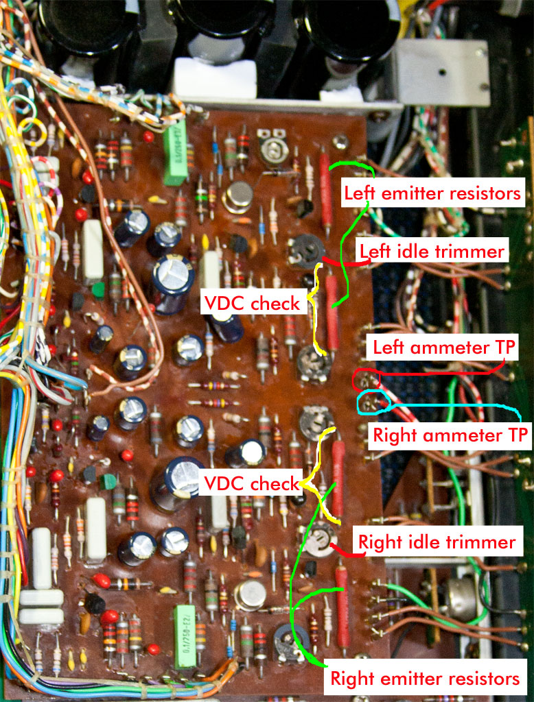
I have been working on my 2408B model. The recap is done. Here is the 8002095 Output Amplifier PCB that has the four extra trimmers. I have marked what I believe are the correct locations for performing the idle DC check. The service manual calls for pulling the left and right output wires (hv/r and r) and using an ammeter to adjust the idle current to 80mA on each channel. Dillen suggested that one can also measure the voltage across one of the emitter resistors instead of pulling the wire off. In either case, do I have the locations marked correctly on the picture?
Thanks, Sonavor
|
|
-
-
sonavor
- Joined on 02-13-2011
- Texas
- Posts 193
|
Re: Beomaster 4000 (type 2408) Circuit Differences
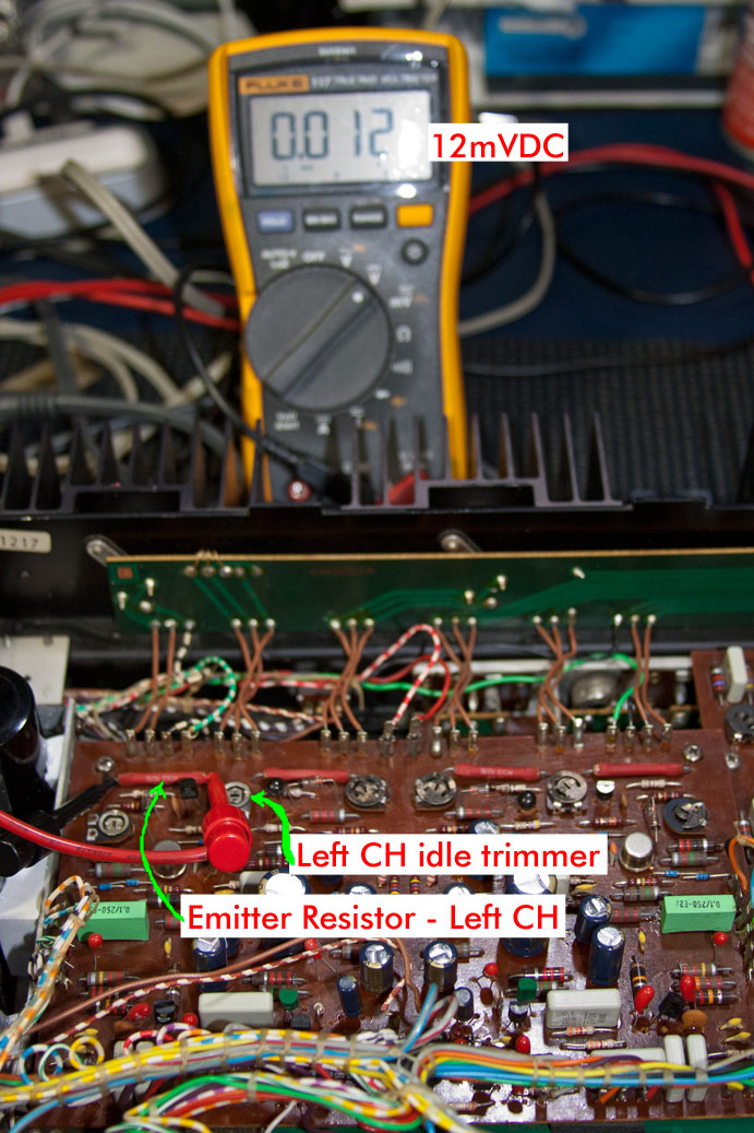
A follow-up....Using my ammeter at the points I showed in the previous photo didn't measure anything so I went with Dillen's recommendation on adjusting for 12mVDC across the emitter resistors. Here are the photos of that.
|
|
-
-
sonavor
- Joined on 02-13-2011
- Texas
- Posts 193
|
Re: Beomaster 4000 (type 2408) Circuit Differences
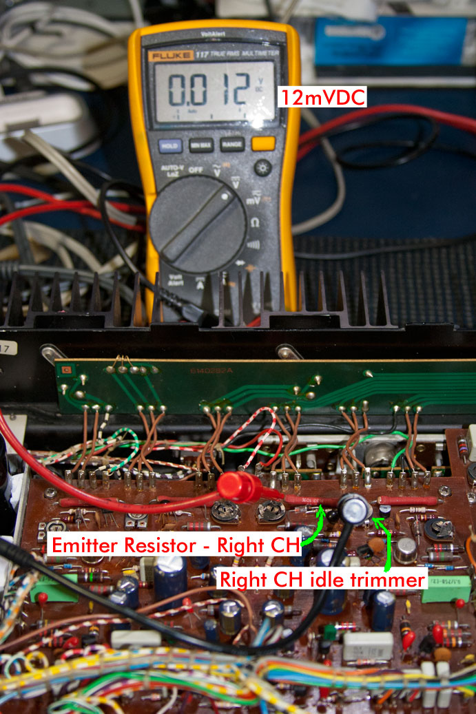
...and the right channel -
|
|
-
-
sonavor
- Joined on 02-13-2011
- Texas
- Posts 193
|
Re: Beomaster 4000 (type 2408) Circuit Differences
I am getting close to wrapping up my two Beomaster 4000 refurbishment projects. I have the first one (type 2408-A) working now. The second one (type 2408-B) is working except for the tuner presets. About my type naming - I am calling Type 2408-A the first modification of the original Type 2406 per the service manual. I am calling Type 2408-B the second mod...the one with the additional four trim pots on the 8002095 Output Amplifier PCB and the new 8002135 resistor board.
In refurbishing these two slightly different versions of the BM-4000 I figured I would show some of the other differences aside from the circuit differences.
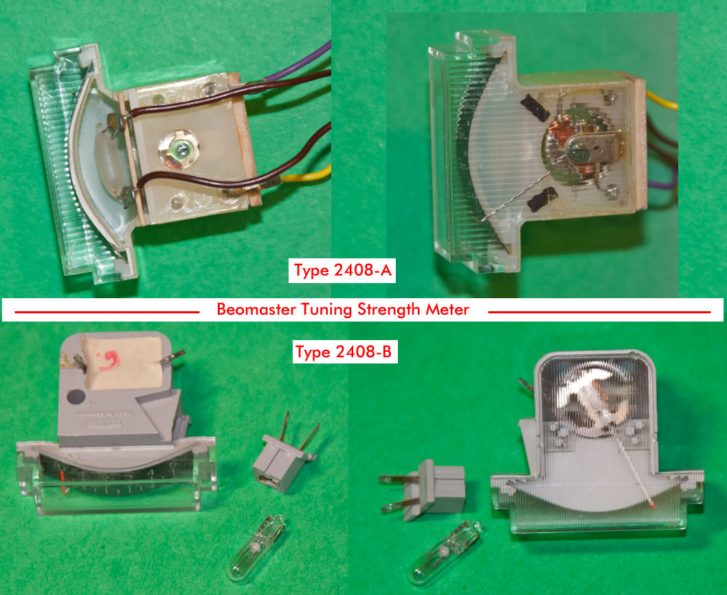
In this picture I show the FM tuner strength meter from both types of BM-4000 units. The thing to note about the difference is that the replacement lamp for the meter is different so when replacing that lamp you need to be aware of that.
|
|
-
-
sonavor
- Joined on 02-13-2011
- Texas
- Posts 193
|
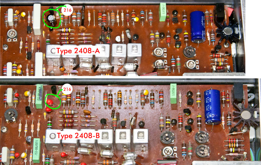
Re: Beomaster 4000 (type 2408) Circuit Differences
Here is a picture of a recap difference between the Beomaster 4000 Types 2408-A and 2408-B. The difference in the picture is that the Type 2408-A IF Decoder PCB (8002058) has an electrolytic capacitor for reference designator 216. The 2408-B has a tantalum (I believe that is what it is). The capacitor value in both cases is the same, 22uF so this wasn't a circuit change between the types...just a component selection difference. If you get a recap kit from Dillen (which I highly recommend) then make sure you let him know if you need the extra electrolytic if you have the Type 2408-A board.
|
|
-
-
sonavor
- Joined on 02-13-2011
- Texas
- Posts 193
|
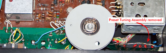
Re: Beomaster 4000 (type 2408) Circuit Differences
I thought I would throw in a picture of my BM4000-2408-B unit where I have the tuner preset module removed. With the preset module removed my main FM tuning works pretty good. With the preset module installed I get all sorts of problems - interference between the tuning pots. I checked the preset tuning pots and they all seem to work fine. The little red tantalum caps all tested good. I think there must be a short somewhere in the flexible PCB that the selection switches connect to. It was such a pain on this particular unit to align the pushbutton switches though that I am finding it hard to motivate myself to take all of that apart again. I believe I put in close to five hours tinkering with the pushbutton installation before I good get all of them to work. On my BM4000-2408-A unit it all went together and worked the first time. I have a spare parts BM4000 that looks like it has a good front panel switch assembly and tuner pot module so when I do get the motivation I will switch the entire front end out.
|
|
-
-
sonavor
- Joined on 02-13-2011
- Texas
- Posts 193
|
Re: Beomaster 4000 (type 2408) Circuit Differences
I think I am about ready to declare my Beomaster 4000-2408A receiver completed. The only thing I haven't connected and checked is a Beocord phonograph. My setup isn't convenient for me to do that right now so it will have to wait. The Tape 1 and 2 inputs work well using an ipod device and the FM tuner is working quite well. It was my first Beomaster 4000 purchase. I was looking to buy one for quite a while when this one came along and I thought it looked great. The main problem with it (other than age) was that it had a vibration in the transformer. I have heard that is common with these receivers but this vibration was really bad...so much that I really couldn't see using it in that condition. I was fortunate to get a spare that is vibration and noise free (no hum or buzz). Here is a picture of the receiver.
One other thing to note - thanks to Dillen and Søren (Mexico). Søren inspired me with his Beomaster 4000 project and Dillen is an amazing resource for parts and B&O knowledge. I wouldn't have completed this without his help. 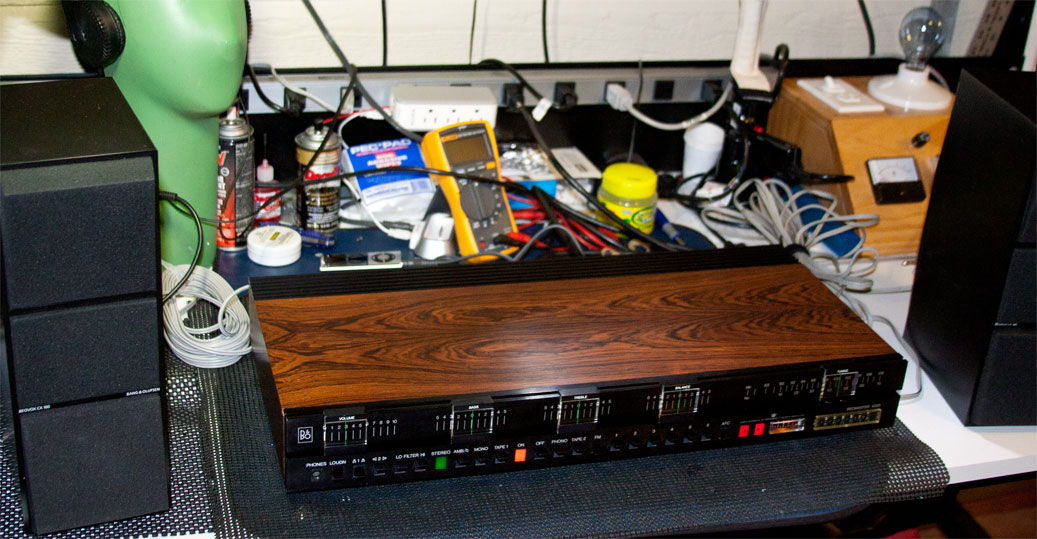
|
|
-
-
Rich
- Joined on 07-10-2010
- Orlando, Florida, USA
- Posts 1,089
|
Re: Beomaster 4000 (type 2408) Circuit Differences
You, sir, are a steely-eyed missileman. Well done, and welcome to the BM4000 club.  
Current primary listening: SMMC20EN -> BG4002 -> BM4000 -> Beovox M70
|
|
-
-
tournedos
  - Joined on 12-08-2007
- Finland
- Posts 5,808
|
Re: Beomaster 4000 (type 2408) Circuit Differences
It is indeed beautiful - I think the folks at B&O took some turns
to ensure the 4000's had good looking veneer! I love mine as well,
unfortunately it suffers from the noisy transformer syndrome too.
Can you tell us more about that instrument in the rear? Looks like a series bulb in a desk power supply?
|
|
-
-
Step1
 
- Joined on 07-06-2008
- Manchester
- Posts 961
|
Re: Beomaster 4000 (type 2408) Circuit Differences
 tournedos: tournedos:
Can you tell us more about that instrument in the rear? Looks like a series bulb in a desk power supply?
An essential piece of equipment for those on a budget :)
|
|
-
-
sonavor
- Joined on 02-13-2011
- Texas
- Posts 193
|
Re: Beomaster 4000 (type 2408) Circuit Differences
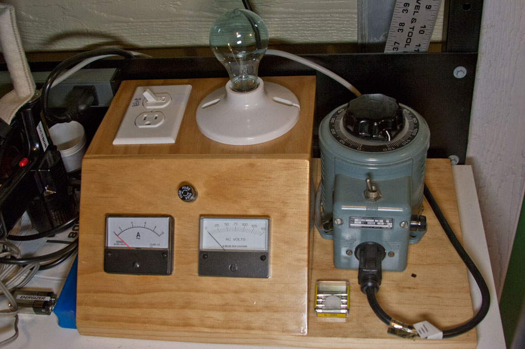
That is my "dim bulb tester" and no, that doesn't mean where I connect myself to when I do something dimwitted like wire something backwards.
It is my variation of a dim bulb tester. I copied the setup from a picture I saw someone else had in their workshop. In case you don't know, the idea of the dim bulb tester is to place a light bulb of a decent wattage (based on what you are testing) in series with the AC power to some device under test. When you apply power to the device, if there is a short circuit to ground, the light bulb will take most of the current and light brightly. If the device is okay, the bulb will initially be bright but quickly go dim...hence the name. So in the simplest form all you need is a bulb socket and a plug for the device you are testing. In the variation I copied there is the addition of a variac to apply the amount AC and two meters (AC voltage and current). I also added a switch to take the bulb out of the circuit so I can use the variac by itself. It has been very useful and lets you check if it is safe to apply power to whatever you are testing. That can save damaging any parts that might still be okay.
During my work on the BM4000, the transformer I replaced my noisy one with initially tested as a short circuit using this dim bulb tester. Dillen told me that it was likely the rectifier circuit that is attached to the transformer. Sure enough, when I removed the rectifier and swapped in the rectifier from my noisy transformer the second transformer tested good...and that is what I ended up using.
Here is a full picture of my dim bulb tester. The device under test is plugged into the outlet plug on the top. The bulb can be switched in or out with the switch next to it. The variac is the bulky thing on the right. The nice thing about the variac is that you can slowly apply AC power if you really suspect the unit to have a short and you can monitor the current draw on the meter. When I was testing the BM4000 transformer with the bad rectifier circuit I could see current being drawn as I applied just a few volts so I knew immediately that something was wrong.
|
|
-
-
sonavor
- Joined on 02-13-2011
- Texas
- Posts 193
|
Re: Beomaster 4000 (type 2408) Circuit Differences
Thank Rich, I am happy to be a Beomaster 4000 member. I think B&O was ahead of their time on this design. It is sleak and modern looking even today yet the slide controls and pushbuttons give it a vintage look that I much prefer over a cold, flat touch screen. I'm not knocking the later B&O receivers that are also great looking but my personal favorite are these BM 3000, 4000 and 4400 models. I say all of that as I am about to start in on a Beomaster 6000 (type 2253) that I got parts from Dillen for. It looks nice too but I still love the seventies receivers.
sonavor
|
|
-
-
Søren Mexico
- Joined on 09-13-2007
- Mexico city
- Posts 1,621
|
Re: Beomaster 4000 (type 2408) Circuit Differences
Back again from my vacation, very good job indeed, and love your explanations, thanks a lot for a good thread, you are way ahead of me, not only in the work, but also in knowledge. I hope to get back to my 4000 in the weekend, did some thinking and drawing reading during the vacation. When I get hold of a used variac I will come back to you for the drawing of your dim bulb tester, saw a simpler version somewhere, but yours is a lot better.
Congrats John, beautiful piece, waiting for your next thread, are you getting infected with the BeoVirus ???
Soren
Beosound 3000, BL 4000, BL 8000, BG 2404,BG 5000, BG CD50, Beocord 5000, BM 901, BM 2400, BM 4000, BV S45, BV 3702. There is nothing we cannot do, but a lot of things we don't want to do!!
|
|
-
-
sonavor
- Joined on 02-13-2011
- Texas
- Posts 193
|
Re: Beomaster 4000 (type 2408) Circuit Differences
Happy New Year Søren.
I built the dim bulb tester a while ago. I will look up the wiring diagram I made or create a new one for you.
I think I am infected with the BeoVirus. I was thinking about it as I was painfully trying to get the switches aligned on the other BM4000 unit. I came to the conclusion that while B&O equipment is often difficult to work on, that challenge is part of the attraction. That and the satisfaction at the end that you have a beautiful piece of equipment working again.
Sonavor
|
|
|
|
|