|
Untitled Page
ARCHIVED FORUM -- April 2007 to March 2012
READ ONLY FORUM
This is the first Archived Forum which was active between 17th April 2007 and
1st March February 2012
Latest post 07-26-2009 3:12 PM by yachadm. 9 replies.
-
 07-23-2009 3:35 PM
|
|
-
 yachadm
 
 - Joined on 06-24-2007
- Jerusalem, Israel
- Posts 687

|
Hi all.
My BM1600 (1973 model) type 2113, started running hot at the rear heatsinks.
I replaced the bias trimpots, and adjusted for 16mV idle current across the 0.39ohm resistors for the left and right channels.
It worked OK for about 1/2 hour, and then the channels started cutting out.
I connected it via a 150W series lamp on the AC mains, to monitor.
Sure enough, the lamp was illuminating occasionally.
I checked the idle current on both channels (L=328mV, R=0.115mV!!!!), and adjusted the trimpots, but it had no effect on the idle current readings.
I then checked the output stages - all transistors checked OK, except for TR41, showing a short.
In the Service Manual, TR41 shows a 2N5034, NPN, but installed is a TO-3 casing RCA 60465 ????? I couldn't find any reference on this, but when I checked TR38 (same one) it is not a "standard" NPN, as it shows a resistor shunt between the Base and Emitter.
The only replacement I can find is a cross-ref on NTE for a NTE390, but this NTE390 is not a TO-3, but like a "large TO-220", so it cannot be mounted on the rear panel.
I have 2N3055's, but I'm not sure that this is an acceptable substitute.
Does anyone have any ideas for a TO-3 substitute?
Menahem
Learn from the mistakes of others - you'll not live long enough to make them all yourself!
|
|
-
-
Dillen
  - Joined on 02-14-2007
- Copenhagen / Denmark
- Posts 5,008

|
Re: Beomaster 1600 Problem
2N5034 is not a TO3. It's a TO219a if my memory serves me right.
It's found in other Beomasters from the same years, Beomaster 1001 etc.
It's pinout can look a bit like a TO3 but it's smaller and the housing
is square rather than eliptical.
I may be able to find some good used 2N5034 but are you sure that the chassis fitting is for a TO3 ?
There should be no parasite resistors inside any of the output stage transistors.
Martin
|
|
-
-
yachadm
- Joined on 06-24-2007
- Jerusalem, Israel
- Posts 687
|
Re: Beomaster 1600 Problem
Hey Martin - Thanks!
I know the old rectangle types to which I think you're referring, but see the picture - these definitely look like TO-3's to me!
Perhaps this is a later version, with these RCA 60465 unknowns.
I can't open up the resistor to check visually  , but my Peak DCA Semiconductor tester claims that there's a shunt there, and added that because of that, the HFe measurement is unreliable... , but my Peak DCA Semiconductor tester claims that there's a shunt there, and added that because of that, the HFe measurement is unreliable...
On the 2N3055, the Peak tester makes no such claim - what do you think?
Menahem. 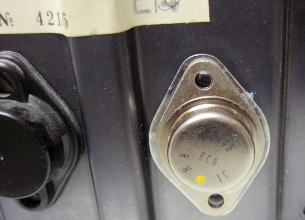
Learn from the mistakes of others - you'll not live long enough to make them all yourself!
|
|
-
-
yachadm
- Joined on 06-24-2007
- Jerusalem, Israel
- Posts 687
|
Re: Beomaster 1600 Problem
I've done some research, and both Motorola and SGS give the 2N3055 as the nearest replacement for the 2N5034.
OK, so that's one thing cleared up, but I'd still like to know what these RCA 60465's are, and why specifically these with shunt resistors were used.
AFAIK, shunt resistors (in Bipolars) are used to smooth out pulses, like in some versions of HOT's (Horizontal Output Transistors) off the flybacks in TV's.
So why would one need a shunted Bipolar here - we don't have high pulses like in a TV?
Menahem
Learn from the mistakes of others - you'll not live long enough to make them all yourself!
|
|
-
-
Dillen
- Joined on 02-14-2007
- Copenhagen / Denmark
- Posts 5,008
|
Re: Beomaster 1600 Problem
Yes, those are indeed TO3's.
B&O have used RCA transistors in the 1960's (Beolab 5000 springs to mind)
but I never came across that type before.
My guess is that they were mounted as being the best option by a previous repairer.
If you can make 2N3055 work with regards to temp. stability and
idle current, which shouldn't be too hard in this relatively low-powered
receiver/amplifier, I would recommend you use them.
2N3055 will probably work fine both in the power supply and the output stages,
it's a tough transistor. And don't worry about it having no built-in resistor, it's not needed here.
Martin
|
|
-
-
yachadm
- Joined on 06-24-2007
- Jerusalem, Israel
- Posts 687
|
Re: Beomaster 1600 Problem
Right on - the 2N3055 does the job - all fixed.
After proper adjustments, it runs really cool (temperature) - it's not even warm!
While I was in there, I replaced the burnt-out stereo light with an LED - bad move!! This is one of those rare times where an LED does not substitute well. Voltages on the Decoder PCB are all over the place, and Stereo sound is very distorted, decoder alignment is a headache.
So, I put in an original 12V 30mA lamp, realigned in about 10 minutes, and the FM is superb.
(The Radicator and Dial lamps were substituted with LED's with no problems at all)
I also realigned the MW and SW.
There is an error in the Service Manual regarding SW alignment. On Page 22, Diagram 8 should be titled "Alignment of SW I ..." On Page 23, Diagram 9 should be titled "Alignment of SW II ...". Until I figured this out, I was adjusting away very frustrated, wondering why nothing was happening!!!!!
A couple of other small items remain to be fixed - the two 500ohm NTC resistors in the output stages are way out - 1 is 190 ohms, and the other is 310 ohms.
Most of the resistors have been replaced with Vishay Dale RN60 units - a big improvement in sound.
As always, thanks Martin, for your expert and kind assistance!
Menahem
Learn from the mistakes of others - you'll not live long enough to make them all yourself!
|
|
-
-
Dillen
- Joined on 02-14-2007
- Copenhagen / Denmark
- Posts 5,008
|
Re: Beomaster 1600 Problem
An NTC resistor changes its value according to the temperature.
NTC stands for Negative Temperature Coefficient, meaning that
the ohmic value will decrease with higher temperature.
(PTC resistors also exists, working the opposite way = Positive ...)
Before measuring NTC/PTC resistors, you will have to make sure that they
are at the same temperature. Even the small current from the ohmmeter can
sometimes cause a warmup of the component enough to cause a change of resistance
so it's quite hard to measure correctly. The factory tolerances can also
be very wide.
The stated resistance of 500 Ohms are only measureable at certain temperature
(and sometimes current) conditions and will practically never be
reflected on the meter as that exact value.
If the amplifiers work and don't do a thermal runaway, I wouldn't worry
about the NTC's.
Martin
|
|
-
-
yachadm
- Joined on 06-24-2007
- Jerusalem, Israel
- Posts 687
|
Re: Beomaster 1600 Problem
Point well taken, but I'm a bit gun-shy of these NTC's right now!
About 6 months ago, my 20-year-old Tek 2465B scope failed. After getting (mad) quotes for repair, I decided that I couldn't lose anything by going at it myself. I got a lot of help from the Tekscopes Yahoo forum, and after about a month of horse-trading, I traced the culprits down to 2 15 Ohm NTC's in the SMPS. When they let go, they took a whole bunch of other components with them.
My Tek is working just fine after I repaired it - cost of parts was less than $100, and I learnt a fortune.
So, I'm going to go ahead and replace them anyway - experience is a bitter teacher! The modern parts should have much better tolerances than the old ones!
Menahem
Learn from the mistakes of others - you'll not live long enough to make them all yourself!
|
|
-
-
richtoy
 
- Joined on 09-20-2007
- Valkenburg, Netherlands
- Posts 184

|
Re: Beomaster 1600 Problem
Hi Menahem
I have just brought a Tektronix 2465BCT, it's a fine oscilloscope as stated here: -
http://www.amplifier.cd/Test_Equipment/Tektronix/Tektronix_other/2465B.htm
If mine goes wrong I'll know who to come to... 
What equipment do you use for setting up RF & IF stages? One of the BM6000 Quads that I have has been "adjusted" by a previous owner (obvious marks on most chokes and caps in RF, detector and decoder stages  ) and I have been struggling to get the RF stage aligned. I have the following: - ) and I have been struggling to get the RF stage aligned. I have the following: -
Philips SBC521 RF signal generator 0.1 - 120MHz AM, FM & sweep
Leader 3216 Standard Signal Generator with Stereo option
Dynatek 10Hz - 1GHz Multi Function Counter
Philips PM5132 Function Generator 0.1Hz - 2MHz
Philips PM5106 LF signal generator 10Hz - 100KHz
Richard
Some of my B&O: BV3/32, MX7000, MX5500, LX5500, MX4000, BM8000, BM6000, Overture, BL8000, BM6000 Quad, BM4400, BM3400, BG-CDX, BM3000, BM1001, BM1200, BM1600, BM1700, BM1500, BM1400, BM2400, BM2300, BM4500, BM4000, BVM70, BVS45-2, BVS60, BC7700, BM2200, BM1900, BG8002, BM1202, BVPenta, BVP45
|
|
-
-
yachadm
- Joined on 06-24-2007
- Jerusalem, Israel
- Posts 687
|
Re: Beomaster 1600 Problem
Hi Richard,
Nice pieces you've got there. I use a Meguro AM-FM Stereo Signal Generator. On the units I work on, I haven't found a need for anything else, except my scope, of course!
You'll need an impedance matcher between your Signal Generator output and the BM6000 antenna input (300ohm).
I made my own (see picture) BNC 50ohm on the SG, to the 300ohm BeoPlug. I used a ferrite 67-binocular-core, but I forgot the number of turns...IIRC, it was 5 turns on the BNC side and 12.5 turns on the BeoPlug side.
Use the Service Manual, - it's written really clearly, and the stages progress logically.
Connect your scope probe to the PCB locations as per the SM, set the VOLTS/DIV and SEC/DIV to give you a large, understandable waveform, and follow the SM. (Did you calibrate your probe to the scope?)
Don't try to do a perfect 100% alignment on the first round - you'll just get frustrated. Get each stage 80-90% aligned, and then move onto each subsequent stage . When you've finished the complete alignment procedure, take a rest and then start again at step 1. Second time around, it all falls into place really easily. That's how I do it, anyway.
Keep the speakers connected - you'll make the connection between what your ears are telling you is a good signal, to what your eyes see on the scope.
I would also replace the 3 10.7MHz ceramic filters - they are like wide-open barn-doors.
Ignore the previous owner's markings.
Be careful turning the ferrite slugs in the coils - I broke a couple of mine....that's another story.
Let us know how you make out!
Menahem 
Learn from the mistakes of others - you'll not live long enough to make them all yourself!
|
|
Page 1 of 1 (10 items)
|
|
|