|
Untitled Page
ARCHIVED FORUM -- April 2007 to March 2012
READ ONLY FORUM
This is the first Archived Forum which was active between 17th April 2007 and
1st March February 2012
Latest post 11-12-2009 12:26 AM by yachadm. 9 replies.
-
 09-09-2009 12:23 PM
|
|
-
 yachadm
 
 - Joined on 06-24-2007
- Jerusalem, Israel
- Posts 687

|
Hi to all BeoFans,
I received this BeoCord 5000 Type 4922 for free (something which doesn't happen too often), after it had been in storage in very bad shape, with lots of rust damage on the casing. It was going to be tossed in the garbage dump.
I'm not a great fan of cassettes (although I have a large collection), and would not actively pursue another cassette deck - I have one BeoCord 2200 - but the BC5000 is generally recognized as the best that B&O made, so I decided, why not!
When I opened it up, there was a lot of signs of white stains, which looked like water damage, and many of the copper conductors and component leads had blue corrosion on them.
So this was definitely not in good condition.
I started with basics, at the power supply to check voltages. Normally I replace all the large ROE power caps, but these are quite expensive, and I was not going to invest in new ones, unless I was certain that this deck was capable of being resurrected, which at this time, there was no such certainty.
So I satisfied myself that the ESR and capacitance of the caps was acceptable, and decided that I was going to make a go/no-go decision if I could get good voltage out of the PSU.
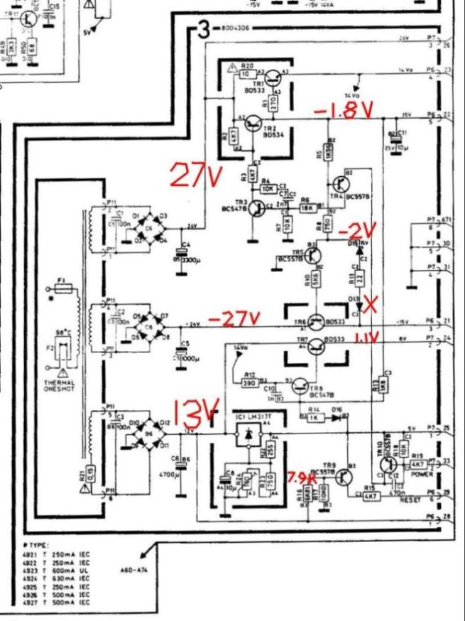
On this BC5000, there are 3 discrepancies in parts on the PSU -
1. an actual 1N4148 does not exist in the D13 mounting holes on the PCB,
2. R16 is actually 7.9K, instead of 6.81K on the circuit diagram,
3. R9 is physically on the PCB, but not on this circuit diagram, so this is probably not the correct SM.
It previously already had the LM317 mod, as described in the SM.
All transistors are checked fully functional, and all passives are checked within limits.
I have already replaced R20 - the infamous 10 ohm fusible resistor.
See the voltage discrepancies in red.
I thought that maybe there was an undocumented modded version of this PSU, or in a different Service Manual, but after exhausting all known resources without success, I realized that I would have to solve this problem on my own.
So, I resoldered all joints on the PCB - still no success, and then I decided to replace the 2 ribbon cables - even though the corroded originals checked continuity OK. I replaced the 1.96K resistor.
And SUCCESS!!!
From the PSU, I got +27VDC, -27VDC, and +15VDC - unloaded of couse, because the PSU was not yet connected to the guts of the BeoCord.
So, i decided that this was now a GO project.
Menahem

Learn from the mistakes of others - you'll not live long enough to make them all yourself!
|
|
-
-
 yachadm
 
 - Joined on 06-24-2007
- Jerusalem, Israel
- Posts 687

|
Re: BeoCord 5000 weird Power Supply
So now, I decided to clean the guts inside.
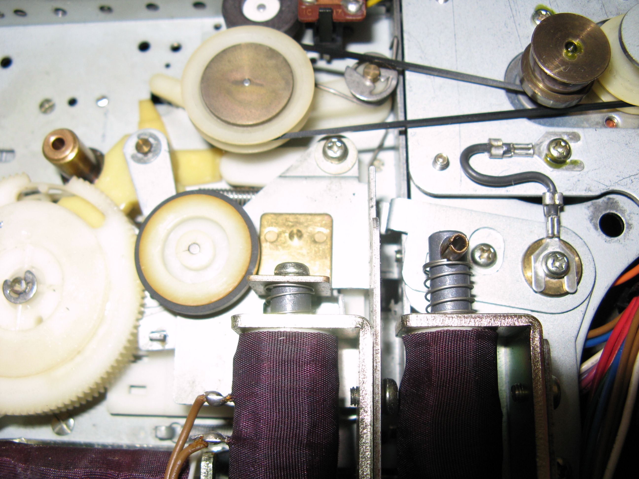
I disassembled the large main PCB, and the Tape Transport - a real disaster - there were no belts, just a large black goo on the motor shafts, and lots of ingrained dust.
The PCB was quite simple - I put it in the bathtub with soapy warm water and brushed it with a large gentle paintbrush. After about 10 minutes, the water was black, and the PCB was clean. I rinsed it with a spray hose, applied compressor air to it, and left it alone to dry for at least 3 days.
The Tape transport was a bigger problem - I realized that I would have to disassemble it completely, if I wanted to do the job properly. So, I took plenty of photos as I dissasembled each part.
On this I am always a bit nervous - because these white plastic parts have a habit of breaking from age! But luckily, none broke.
Then the transport went into a soapy tub, with the same brush. Afterwards, I used lots of alcohol to remove the black goo. Then I sprayed all the plastic parts with Silicon Spray - much better than the white grease, which attracts dust, and hardens over time.
It took me a long time, and I made mistakes, but eventually, I had reassembled the shiny Tape Transport again.
I put on the new belts from Martin, and hoped for the best. 
Learn from the mistakes of others - you'll not live long enough to make them all yourself!
|
|
-
-
 yachadm
 
 - Joined on 06-24-2007
- Jerusalem, Israel
- Posts 687

|
Re: BeoCord 5000 Restoration
So, I reassembled the main PCB and the tape transport into the casing.
Bear in mind that this is still very much exploratory at this stage - even though the PSU is producing good power, the PCB is clean, and the Tape transport should work OK, I still have no idea of the electrical/electronic condition of the BC's functions.
So, I connected AC power, and hoped that nothing would vanish in a puff of smoke!
Well, immediately, without touching any buttons, the RECORDING light on the front panel illuminated, and the transport started fast forward.
Pressing the tape control buttons had no effect.
Then I smelt some smell of heat!!!!
I immediately switched off the power, and by coincidence, I touched the DIP40 IC1 - it was very hot. The first thing which entered my mind, of course, was a defective IC, and no ways will I find one.
Then I thought, based on experience, generally these old IC's don't just fail by themselves, there is usually some external cause.
So, I removed the IC from its socket - good thinking B&O designers - reapplied AC power, and measured each socket pin for DC voltage.
I wrote the values down, and went back to the service manual. I compared the measured voltages to the SM voltages, and NOTHING matched.
Now I really needed to take a break - this is a real problem!
Learn from the mistakes of others - you'll not live long enough to make them all yourself!
|
|
-
-
 yachadm
 
 - Joined on 06-24-2007
- Jerusalem, Israel
- Posts 687

|
Re: BeoCord 5000 Restoration
I got out on my bike, and tried to sort things out with this problem, but nothing came.
I got back to my workshop - I looked again and again at the picture with the voltages, and then something caught my eye - when I looked at the my voltage picture UPSIDE DOWN, it appeared to match the voltages in the SM!!!!!!
OK - get this - are you ready?
B&O installed a DIP40 socket onto the PCB. But they installed it backwards!!!! The socket's notch is on the wrong side!!!! Now, during production, the worker who installed the IC into the socket, probably noticed it, but decided to keep quiet. At some point in the past, some repairer removed the IC, and replaced it in the same (wrong) orientation as the socket, and promptly declared the deck as unserviceable!!!
So, I replaced the IC in the opposite orientation as before, applied AC power, and the counter and red standby-light lit up, as normal - I inserted a tape, pressed all the tape control buttons, and everything operated.
Wow!
Best of all - the IC is cool, not even warm, and proof that this IC can survive after being inserted the wrong way!!!!
Now I looked at the L&R channel indicators on the front panel, and saw that only the R channel's LED's were indicating. Nothing from the left.
I checked the wires at the Tape-head with my scope, and all were putting out a signal. So, something in the electronics was no good.
Here's where I took a deep breath - the issues of investment in time and parts were now applicable. At this point, I normally go for a complete recap, and necessary troubleshooting for the dead left channel, along with other possible electronic defects.
I decided that based on the current working condition of the deck, I would go ahead.
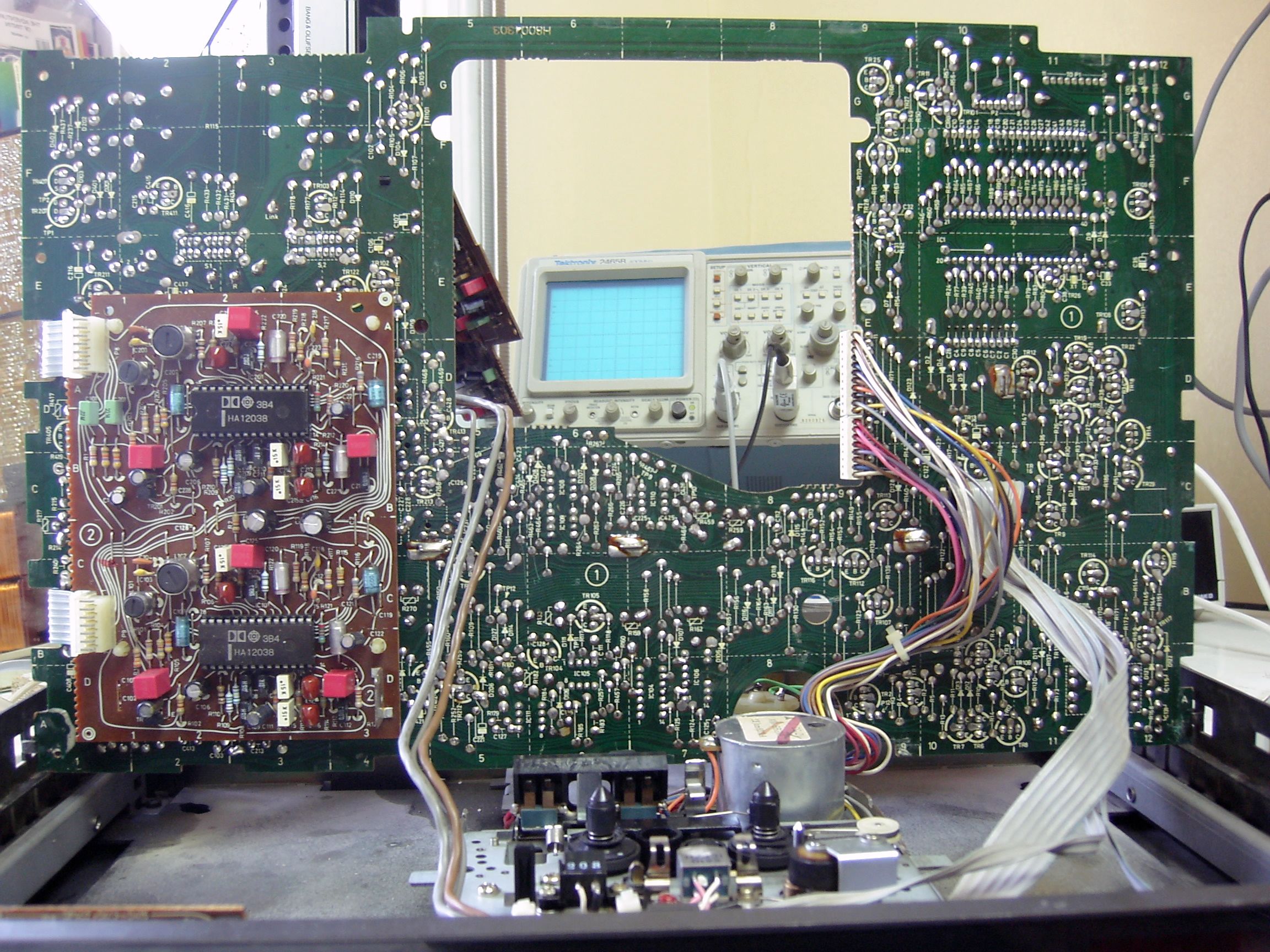
So here, you can see the deck, with the PCB in the service position. 
Learn from the mistakes of others - you'll not live long enough to make them all yourself!
|
|
-
-
 yachadm
 
 - Joined on 06-24-2007
- Jerusalem, Israel
- Posts 687

|
Re: BeoCord 5000 Restoration
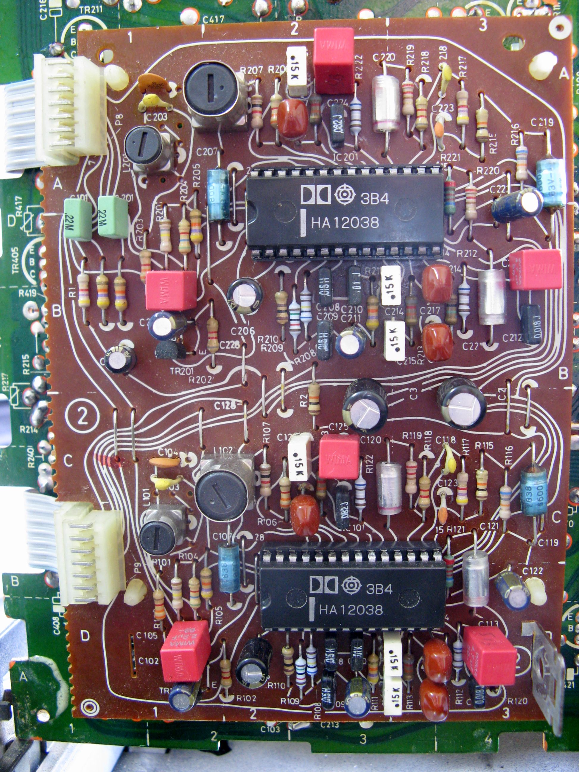
I replaced all the electrolytic caps on all the PCB's with WIMA MKS2's and Panasonic FM and polyesters. All the Trimpots were replaced by Bourns Cermet trimpots.
I must emphasis here a very important point - I do not have any of the Test tapes which the SM specifies, in order to do all the alignment and adjustments, so when replacing each trimpot, I measured the old trimpot's exact resistance, and set that exact resistance on the new trimpot. Generally that works quite well, as long as a previous tech did not go mad, willy-nilly adjusting trimpots not knowing what he was doing.
Here is a closeup of the Dolby PCB. All the new capacitors are quite visible! 
Learn from the mistakes of others - you'll not live long enough to make them all yourself!
|
|
-
-
 yachadm
 
 - Joined on 06-24-2007
- Jerusalem, Israel
- Posts 687

|
Re: BeoCord 5000 Restoration
After I installed all the new caps, and reassembled the deck, of course I wanted to hope that the Left channel would now be working!!!
No luck!
So, I started tracing the signal path with my scope, and pretty shortly came up with no signal at trimpot R417 - the output signal adjustment. I poked around in that area, and came up with a bad cap C407 10nF. I replaced it, and voila - the Left channel LED's sprang to life!
Now, I connected the deck to my BM3400, to hear the sound for the first time. It was pretty dark and thin, as if there was no life to it. I went to the tape head, and adjusted the height alignment screw - yes - now it sounds like it should!
The motorized tray gave me a bit of a challenge, until I figured out the the motor rotates clockwise with one press of the front-panel, anti-clockwise with another press and so on. So, to get the motor in-phase with the drawer, I disconnected the green socket on the PCB, pressed the front panel once, and reconnected the socket.
So overall, I am quite happy with my new addition - the cosmetics are not great - quite scratched, but under the lid, it is now in as-new condition.
Here is a view of the restored main PCB. 
Learn from the mistakes of others - you'll not live long enough to make them all yourself!
|
|
-
-
 yachadm
 
 - Joined on 06-24-2007
- Jerusalem, Israel
- Posts 687

|
Re: BeoCord 5000 Restoration
There is one outstanding issue which I'd like to take of - one red LED segment on the 4-digit counter is inop.
Does anyone know how to repair these? 
Learn from the mistakes of others - you'll not live long enough to make them all yourself!
|
|
-
-
 tournedos
  - Joined on 12-08-2007
- Finland
- Posts 5,808

|
Re: BeoCord 5000 Restoration
 yachadm: yachadm:
There is one outstanding issue which I'd like to take of - one red LED segment on the 4-digit counter is inop.
Does anyone know how to repair these?
Not me, but it seems like a custom module you obviously cannot get from anywhere but another Beocord 5000. Internally, I'd bet it's very similar to the LED displays in 6000/8000 series - i.e bare substrate LEDs bonded straight on the PCB. So a similar job, only much harder due to the smaller size 
|
|
-
-
 Friedmett
 
 - Joined on 04-28-2007
- Herning, Denmark
- Posts 840

|
Re: BeoCord 5000 Restoration
As for B&O making a mistake I would like to say that the production line is mainly in a circle with the workers (ladies for the Beosound 9000 a few years ago) with the B&O comming on rails, then stopped for a job like insert a printboard or other stuff then send on to the next person by rails. It hen ends up at the packing machine and put in a B&O box. After that cleared and by rails up under the ceiling of the factory to the main storage.
Whoever did the actual printboard is the culprit but it can't have been done while it was put together. Maybe the printboard was made in the factory in Skive which were closed.
Otherwise great thread!
|
|
-
-
 yachadm
 
 - Joined on 06-24-2007
- Jerusalem, Israel
- Posts 687

|
Re: BeoCord 5000 Restoration
Hi Frede
Thanks so much for your compliment!
Actually, if you look at the picture above, you can see that the IC's printboard markings are correct.
The socket was inserted in reverse.
The socket's pins numbers are also engraved in the plastic from 1-40. When working on PCB's, one's first inclination is to go with what is seen easily - ie the socket's notch.
Only afterwards, did I actually see the 4 correct numbers (1, 20, 21, 40) on the printboard! And of course, those do not match at all with the numbers on the reverse socket!
If I really had nothing to do, I'd desolder the socket, and reinstall it correctly. But that is not a priority now!
Menahem
Learn from the mistakes of others - you'll not live long enough to make them all yourself!
|
|
Page 1 of 1 (10 items)
|
|
|